174
•
Ventilation must be sufficient.
•
If ventilation is not sufficient, the indoor air humidity
will rise, which can cause condensation on cold
surfaces.
•
The indoor air humidity levels must be checked at
regular intervals.
•
The recommended relative room air humidity is
40–45% at most (with room temperature at 20–22°C).
By adhering to these values, the indoor air humidity
remains at a healthy level and the risk of condensation
lowers significantly. Humidity can be measured with
a hygrometer. When air humidity rises over 45%,
ventilation must be boosted. When air humidity drops
under 40%, ventilation can usually be reduced.
•
The cleanliness of filters must be checked regularly.
•
In winter, the exhaust air filter collects dirt faster
than the replacement air filter. This means that the
replacement air flow is reduced, which can lead to a
rise in indoor air humidity, which in turn weakens the
efficiency of heat recovery.
•
Check monthly that the heat exchanger is functioning
correctly, i.e. rotating.
•
If ventilation unit is not used for a long time, it can
be shut down as long as the fresh air intake vent and
exhaust air blowout vent are covered.
•
This prevents humidity from condensing on the
electric motors of blower, for example.
•
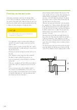
In the autumn, before the beginning of heating
period and before beginning cooling (if the unit has
a cooling function), the condensation water sewage
functionalities must be checked by pouring water in
the condensation water sewer and making sure that
the water drains away.
General instructions
Do not shut down the ventilation unit. The
ventilation unit must always be kept in operation
at the power level set by the ventilation system
designer.
NOTE
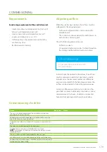
Using the eAir control panel
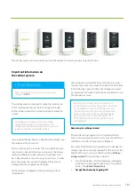
Ventilation is used primarily with modes. The modes in use
can be seen in the control panel main screen. The user can
choose the best mode for each situation: At home, Away,
Boost, Overpressure, Silent, or Max. cooling / Max. heating.
The Silent and Max. cooling / Max. heating modes must
be activated separately from the Settings > Modes menu
before they are shown in the Modes menu. The Modes
menu can be accessed by tapping the round button in
the middle of the control panel main screen.
Eco mode can be activated in all modes except in Max.
cooling / Max. heating mode. Eco mode stops post-
heating and active cooling, and maximizes the use of heat
recovery. Heat recovery is 100% until outdoor temperature
reaches the outdoor temperature limit of heating, or until
supply air temperature reaches the supply air temperature
maximum limit. If the supply air temperature drops below
the minimum temperature, post-heating activates and
keeps the supply air temperature at minimum level.
The circle around the operating mode button changes
its color depending on what the ventilation unit is doing.
The circle is green when heat recovery is active; orange
and red when heating is active, and blue when cooling is
active.
The other functions of the ventilation unit can be found
in the Main menu. The menu can be accessed by tapping
the arrow at the bottom of the control panel main screen.
The main menu consists of the following submenus:
Time programs, Measurements, Alarm, Settings, System
information, Maintenance, and eAir web settings For more
information on menus, see the Instructions.
If the system has an automatic alarm, it is shown in yellow
in the control panel main screen. The most common
alarm is the one about changing filters. The reason for the
alarm must always be checked. Check the Alarms menu
for the possible reason for the alarm and the instruction to
how to acknowledge it.
Summary of Contents for LTR-3 eAir
Page 8: ...8 Kanavaliitännät ulkoilma tuloilma poistoilma jäteilma ...
Page 20: ...20 11 13 9 12 Lisävaruste 1 2 min 10 ...
Page 48: ...48 ...
Page 51: ...51 Ammattilaisen asennusohje ...
Page 52: ...52 LTR 3 eAir Installationsanvisningar för ventilationsaggregat Svenska ...
Page 58: ...58 Kanalanslutningar uteluft tilluft frånluft avluft ...
Page 70: ...70 9 13 15 11 10 14 Extra tillbehör 1 2 min 12 ...
Page 98: ...98 ...
Page 101: ...101 Installationsanvisningar för yrkesfolk ...
Page 102: ...102 Installeringsinstruksjoner for ventilasjonsenheten Norsk LTR 3 eAir ...
Page 108: ...108 Kanalkoblinger utendørsluft tilluft avtrekksluft avkastluft ...
Page 120: ...120 9 13 15 11 10 14 1 2 min 12 ...
Page 148: ...148 ...
Page 151: ...151 Installasjonsinstrukser for fagfolk ...
Page 152: ...152 LTR 3 eAir Installation instructions for the ventilation unit English ...
Page 158: ...158 Duct connections outdoor air supply air extract air exhaust air ...
Page 170: ...170 9 13 15 11 10 14 Extra 1 2 min 12 ...
Page 198: ...198 ...
Page 203: ...203 Koblinger Connections ...
Page 204: ...204 ...
Page 205: ...205 ...
Page 206: ...206 ...
Page 207: ...207 ...
Page 208: ...208 ...
Page 209: ...209 ...
Page 210: ...210 ...
Page 211: ...211 ...
Page 212: ...212 ...
Page 214: ...214 eAir W Periaatekaavio eAir W Principschema eAir W Prinsippskisse eAir W Principle schema ...
Page 215: ...215 ...
Page 218: ...218 ...
Page 219: ...219 ...

