10
171 755 02 06-01
05. MAINTENANCE
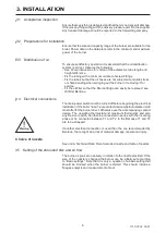
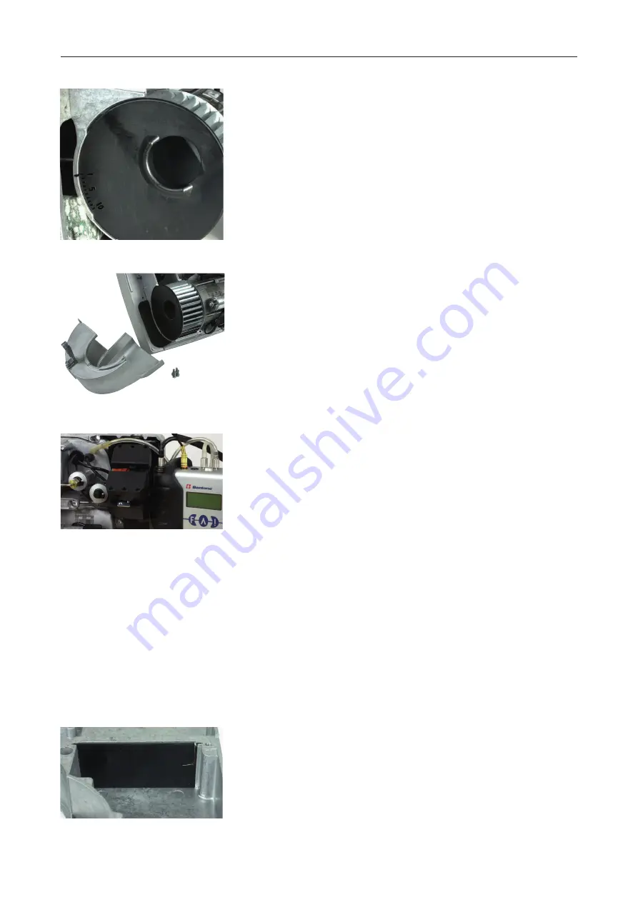
Suction plate
In the case of higher power, as well as with boilers featuring overpressure
in the combustion chamber, it is possible to achieve higher fan pressure
by altering the position of the suction plate, see illustration. The plate is
located beneath the outer half of the fan housing, see illustration, Clea-
ning the fan wheel.
Position 1 is normally used for nozzles up to 0.60 gph and position 4 for
larger nozzles. Position 2 and 3 are intermediate positions. Position 5
and higher does not give more pressure and they are not used.
Check that the plate is placed in the correct position. Otherwise the air-
cannot be adjusted to the correct value.
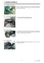
Cleaning the fan wheel
Unscrew the four fastening screws. Remove the half of the fan housing.
Check the position of the suction plate (position 1 up to and including
0.60 gph nozzle). Remove the suction plate. Inspect and clean the fan if
necessary. Rei tting the suction plate is made easier by tilting the burner
forward.
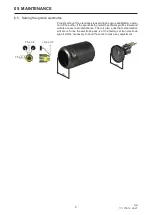
Trimming
If the size of the nozzle is changed, it is suitable to i rst set the nozzle
assembly and air according to the recommendations in section Basic set-
tings. For the individual boiler installation, adjustments can then always
be made to optimise economy, operational reliability and environmental
effects.
The most important instruments for the task are one instrument for l ue-
gas analysis and a soot meter.
The principle of the adjustment is:
- reduce the air, either with the air regulation or the nozzle assembly,
until a soot coefi cient 0.5–1 is achieved.
- increase the air to give a safety margin of 0,5-1% CO
2
before soot is
created. To throttle more with the shrouded disc (smaller reading on
the nozzle assembly scale), gives a short, more bluish l ame and often
better combustion, but if one goes too far there will be starting problems.
Throttling less with the shrouded disc gives a longer and more yellowish
l ame and can give a smoother start.
The pressure in front of the shrouded disc can be utilised as an aid in
the adjusment. Recommended pressure, see under Basic settings. Re-
member to rei t the rubber gasket on the pressure outlet after making
the adjustments.
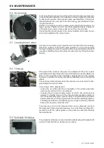
Automatic air damper
The automatic air damper is provided with a small spring at the right shaft
journal. Check that the air damper moves easily.
backwards and rotate it ca. 90° clockwise.
Pump fi lter
When changing pump i lter, see chapter 06.
5.6 Suction plate
5.7 Cleaning the fan wheel
5.8 Trimming
5.9 Automatic air damper
Summary of Contents for Bentone B1FUV Classic
Page 19: ...19 9 DECLARATION OF CONFORMITY...
Page 21: ...21...
Page 22: ...22...
Page 23: ...23...
Page 24: ...Enertech AB P O Box 309 SE 341 26 Ljungby www bentone se www bentone com...


