


4. CONNECT AND LINK OTHER PRINCIPAL CCM DEVICES TO
THE CCMASTER THROUGH MODBUS RTU VIA RS-485
4.1 PHYSICAL CONNECTION
It is possible to connect different Principal CcM devices to the CcMaster, so that the latter can
interrogate them and collect their data. To do this, it is necessary to carry out the process of
linking these devices to the CcMaster and assigning a unique address (ID) to the RS-485 (Mod-
bus) bus.
To link other Principal CcM devices (CcM2 and CcM4) to the CcMaster, different from the Princi-
pal CcM device that powers it through the NDsp connector, it is neccesary to use the ND connec-
tor by following the steps below:
4.2 DYNAMIC ADDRESS ASSIGNMENT BETWEEN DEVICES AND
THE CCMASTER
1.
The black button on the front of the CcMaster (multifunction
button) shall be pressed for 2 to 5 seconds, until the LED A (Blue)
starts to flash. At that time, the button shall be released. The led
should remain blinking.
2.
Press the black button on the Principal CcM (located between
the two connectors) to be linked to the CcMaster until the blue LED
of the Principal CcM device starts flashing. At that moment, the
button should be released. The device would flash, indicating that it
has received a correct Modbus RTU address from CcMaster and is
connected to the CcMaster Native bus. The CcMaster will automati-
cally assign address ‘2’ and so on.
3.
It is necessary to repeat the previous step successively for all the
Principal devices to be connected to the CcMaster.
Principal CcM devices have the Modbus ID '1' by default. Therefore,
the Principal CcM device connected to the NDsp port and powering
the CcMaster keeps the ID '1', and the address of the rest of the CcM
devices connected to the ND port must be changed, since both
ports share the same bus and are internally connected.
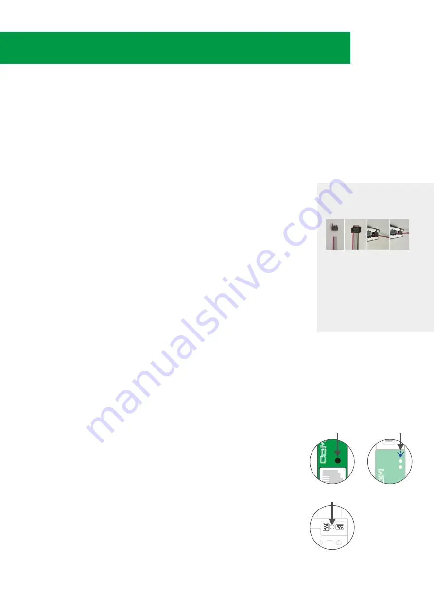
1.
The remaining Principal CcM devices (CcM2 and CcM4) to be con-
nected to the CcMaster, are connected through the ND connector
of the CcMaster. To do this, the 4-wire flat cable and the black con
-
nectors are included in the CcMaster kit shall be used. The connec-
tors shall be crimped to the flat cable at the desired distance from
the CcMaster.
(note 9)
Subsequently, one end of the cable is connected to the CcMaster in
the ND connector.
2.
The intermediate connectors of the cable are connected to the
black connector (and not the red one) of the Principal CcM devices
to be linked to the CcMaster
(note 10)
NOTE 9:
Crimp the connector with the tab
that protrudes over the red-coloured wire
that is part of the 4-wire cable supplied
with the CcMaster.
NOTE 10:
It is very important
TO NOT
CONNECT the cable that converges in
the ND connector of the CcMaster to the
RED connector of the Principal CcM
device since this RED connector has
power and would break the CcMaster by
applying power to the communication
port,
it must be connected to the black
connector of the Principal CcM device that
only contains an RS-485 data port
6
aster
CCM PRINCIPAL BUTTON
PRESS 2-3 SEC
MULTIFUNCTION BUTTON
PRESS 2-5 SEC
FLASHING LED A
(BLUE)
aster


