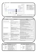
5
Code
Connectors
Device
Characteristics
IN
P
U
TS
S1
S1
Water Probe
Sensor NTC10K@25°C
Functioning temperature 0÷120°C
Misure Range 0÷99°C
LP
LP
Low Pressure Contact
Contact Open/Closed
HP
11
High Pressure Contact
Contact Open/Closed
12
O
U
TP
U
TS
3
N
Pump
Power 230 Vac
Max 3A 230Vac
4
F
ON
5
N
Electrical Heater
Power 230 Vac
Max 3A 230Vac
6
F
OFF
7
F
ON
8
COM
Compressor
Free contact
Max 8A 230Vac
9
N.C.
10
N.O.
LINE
1
F
Input Line
230 Vac
10% 50 Hz;
Protection Fuse T3,15 A
2
N
Absorbed Power:
2VA
Applied rules:
EN 60730-1 50081-1 EN 60730-1 A1 50081-2
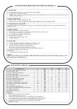
1 - ON/OFF
The ON/OFF of the controller is performed by the extended pressure of the button K4
The OFF state is signaled by OFF of the display and all leds
The ON state is signaled by the led
L9
ON.
2 - START/STOP operations in ON state
Fill the tank with water and expel any existing air, opening a hot water tap.
The START/STOP of the operations is through the extended pressure of the button K3 (CP).
The STOP is signaled by the led
L9
blinking.
3 - Visualizations:
The display shows:
L4 ON >> C01=1 Auto mode ON (configuration)
L1 Blinking >> when timer T01 run (compressor timer)
L6 Blinking >> when timer T02 run (error LP timer)
L7 Blinking >> when timer T03 run (error HP timer)
D1>>Currently the Probe Temperature
D1>> Damages or Alarms signaling
Lo: out of range to the low temperature (under 0°C): Probe broken
Hi: out of range to the high temperature (over 100°C): Probe in short circuit
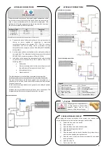
Check the following conditions before implementing the electrical connections:
a)
The thermodynamic equipment should only be powered electrically after the tank has been filled.
b)
The thermodynamic equipment should be connected to monophasic voltage (230 VAC / 50 or 60Hz)
c)
Connections should always comply with the installation regulations in force in the country in which the thermodynamic equipment is installed.
d)
The equipment must be connected to an electrical socket which has been grounded.
NOTE:
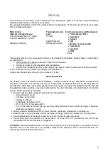
The Solar Box equipment have a relay to allow the connection of a backup electric resistance with
maximum power of
3kW
.
ELECTRICAL CONNECTIONS
ELECTRONIC PANEL (EXTERNAL ASPECT AND CONNECTIONS DIAGRAM)


