4
Vented Installation
HYDRAULIC CONNECTIONS
Procedures for the hydraulic connection of the circuit:
a)
Connect the water inflow and outflow of the equipment with
tubing or joints capable of supporting a combined
temperature/pressure of a constant 75°C / 7 bar. For such we
recommend the use of tubing which is resistant to high
temperatures and pressures, such as PEX, PPR, MULTICAMADA,
among others.
b)
A safety valve needs to be installed at the cold water inflow of
the equipment. The safety device should comply with standard
EN
1487:2002, maximum pressure of 7 bar (0.7 MPa)
c)
In addition to this device other components need to be installed
to guarantee the interruption of the hydraulic load, in the
following order:
Reflux valve
Pressure reducing valve (in the event the pressure of
the cold water inflow is greater than 4.5 bar)
Safety/exhaust valve
Expansion vessel
The safety/exhaust valve should be connected by tubing with a
diameter which is never less than the cold water inflow connection.
The part of the exhaust should be connected to an interceptor, or, in
the event this is inviable, raised at least 20mm above the floor to allow
for visual inspection.
All the above recommendations are to guarantee the safety of people,
animals and others.
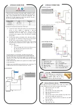
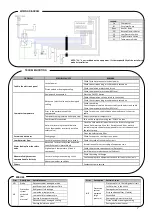
SolarBox may be installed in tanks with two or more connections. The
diagrams below illustrate two types of connection to a tank:
PURGE HYDRAULIC CIRCUIT
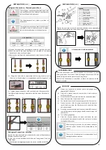
“y” FILTER
After doing the correct installation of the system, the installer must
purge all the hydraulic circuit before turning on the Solar Box.
a)
Ensure that the valve 1a is closed
b)
Close de valve 1b
c)
Open the bleed valve inside the Solar Box
d)
Open the discharge valve (drain) 7
e)
Open valve 1a
f)
Close the bleed valve inside the Solar Box (only when there is
water with no bubbles leaving the valve)
g)
Close the valve 1c (only when there is water with no bubbles
leaving the valve)
h)
Open the valve 1b
i)
Turn-on the Solar Box
HYDRAULIC CONNECTIONS
Tank with more than two connections
WARNING
The equipment is supplied with a
“y” filter placed on the SolarBox
hydraulic return line, at the
entrance of the heat exchanger.
WARNING/DANGER
The water used may contain impurities and/or substances which
are harmful to the system and to the health. Check the water being
used is of an acceptable quality for domestic consumption. The
table below illustrates certain parameters beyond which the water
should be subjected to chemical treatment.
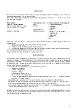
Hardness (ºdH)
pH
Treatment
3.0 to 20.0
6.5 to 8.5
No
3.0 to 20.0
<6.5 or >8.5
Yes
<3.0 or >20.0
--------------
Yes
Tank with two connections
Tank with backup connections
Legend:
1 Open/closed Valve
7
Drain
2 Non return Valve
A
Mains Water
3 Pressure Reducing Valve
B
Hot Water Outlet
4 Security Group
C
SolarBox
5 Expansion Vessel
D
Thermodynamic Panel
6 Filter
S1
Temperature Probe


