


2
WARNING
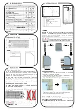
The panel should always be installed
downwards, with the connections facing
down.
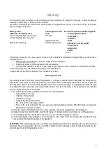
SolarBox
Thermal power supplied
(med-max)
W
1690 - 2900
Power absorbed
(med-max)
W
390 - 550
Electrical power
V/HZ
230/50-60
Operating temperature
°C
-2 to 42
Cooling fluid / Load
-/Kg
R134a / 0.8
Maximum water temperature
°C
55
Maximum operating pressure (water)
bar
7
Weight
Kg
23,5
Size of the packaging
a
x
l
x
p 470 x 400 x 400
Hydraulic connections (input|output)
Inches
1/2” | 1/2”
Refrigerant connections (input|output)
Inches
3/8
"
| 1/4"
Thermodynamic Solar Panel
Weight
Kg
8
Size of the packaging
a
x
l
x
p 2200 x 810 x 30
Refrigerant connections (input|output)
Inches
1/4” | 3/8”
Tank Requirements
Maximum Tank Capacity
lts
300
Minimum Coil Area (when using backup
connections)
m
2
1,5
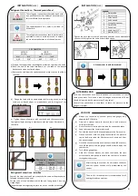
[1]
Aluminium bracket
[2]
Bushing
[3]
Self threading screw M6x4
[4]
Washer M6
[5]
Screw M6x20
[6]
Nut M6
[7]
Panel
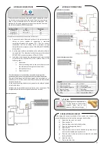
SolarBox
Placing the SolarBox on a horizontal surface
SolarBox
may be fixed to a wall using the four holes in the back or
placed on a horizontal surface using the four silentblocks. In either case,
the device should be correctly levelled. SolarBox has holes at the
bottom (1) and half-holes in the back (2).
WARNING
When installing SolarBox, ensure the wall in question
is capable of supporting the weight of the same.
Fixing SolarBox to the Wall
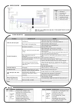
A - Liquid B - Suction
TECHNICAL FEATURES
DIMENSIONS
1 – Make four holes to receive the nuts corresponding to the four M6
flanged screws included in the packaging.
2 – Screw in the screws leaving a distance of approximately 3mm
between the wall and the flange of the screw.
3 – Align the SolarBox and rest the same gently on the 4 screws.
4 – Tighten the screws until they are in contact with the structure.
5 – Secure the connections underneath the structure.
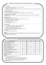
Thermodynamic Solar Panel
SolarBox
1 – Lay the structure on a level and stable surface, checking the four
anti-vibratory brackets have been duly mounted.
2 – Remove the half holes from the rear of the structure by twisting the
metal part you wish to remove.
3 – Secure the connections on the rear of the structure.
The location and the angle at which the panels are installed must be
taken into account. In order to take full advantage of the solar radiation
in question, the panels should be set at an angle of between 10° - 85° to
the ground, and preferably pointing south.
The panel comes with six M8 holes on the side flaps. The distance
between the holes at the location where the panel is to be placed
should coincide with the holes in the panel.
The equipment comes with 3 small and 3 large brackets which should be
fixed in order to give the panel the desired angle.
The brackets should be fixed to the base (e.g. a tile) using the plastic nut
and self-threading M6 screw supplied.
The panel is fixed to the brackets using the M6 screws and respective
nuts and washer.
A
B
INSTALLATION
(cont)
Thermodynamic Solar Panel
Fixing the brackets
Fixing the bracket to
the panel
On the Wall
On Horizontal Surface
1
2
INSTALLATION


