background image

38

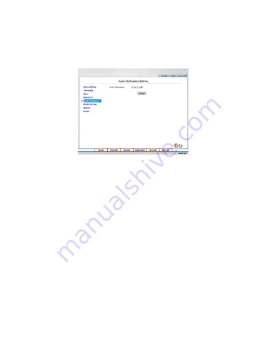
•  Change the System Setting - Audio Mechanism

Please follow the steps below to change the Audio Mechanism through the network if necessary.

.  Click the 

Audio Mechanism

 button on the left side of the „System” page to enter the „Audio Mechanism   Setting”  

  page.

.  Mark „Audio Mechanism” „ON” or „OFF”.
3.  Click the 

Submit 

button to submit the new user’s setting.

4.  Click the 

Home 

button to return to the home page.

  NOTE:  This setting is for turning the audio mechanism of the Videor Server on/off automatically.

Description of function keys

Audio Mechanism:

 Select „ON” or „OFF” to activate or deactivate the function.

Summary of Contents for GLS-2202H

Page 1: ...Installation and Operating Manual Network 1 Channel Video Audio Server MJPEG H 264 Ethernet GLS 2301H...

Page 2: ...re your Video Server Network Settings 14 5 2 1 Enable DHCP Function 14 5 2 2 Set IP Address 14 5 3 TCP IP Communication Software 15 5 4 TCP IP Installation 16 5 5 TCP IP Configuration Setting 17 5 6 C...

Page 3: ...bration Do not place any heavy objects on the unit To disconnect the power cord of the unit pull it out by the plug Never pull the cord itself Pay attention when laying the connection cable and observ...

Page 4: ...SB interface is for basic network setting and updating The SD card slot supports alarm and event recording and updating Furthermore this encoder board comes with the Power over Ethernet PoE function a...

Page 5: ...t indicates the network data are transmitting 3 Reset button Recover to factory default 4 SD CARD Slot This is used for system software updating and archiving accessing critical images 5 Status indica...

Page 6: ...connector Video out connector This BNC connector provides a video signal to the main monitor 3 ETHERNET PoE Connector This is a standard RJ 45 connector for 10 100 Mbps Ethernet networks PoE Power ov...

Page 7: ...d in the menu system to Normally Open or Normally Closed 5V 0V Active 12 GND3 Ground Contact 13 AUDIO IN Connector The connector is used to connect the audio output from a camera or other devices 14 A...

Page 8: ...u want to do with your SD card In another words if the user connects the Video Server with an SD card and the PC via the USB connector the Video Server can be used as a normal card reader 2 As a confi...

Page 9: ...6 7 8 Load Voltage DC Load Connec tor IEEE 802 3af using data pairs 48VDC protected RX DC RX DC TX DC spare spare TX DC spare spare embedded Industry Standard for embedded PoE IEEE 802 3af using spar...

Page 10: ...ssages shown on the screen and inform your technical support while ignoring the following steps 10 Power off the Video Server when this update process is finished then remove the SD card from the Vide...

Page 11: ...ort and ignore the following steps 4 Please make sure the function of SD CARD ENABLE is activated in the ALARM and SCHEDULE pages if no cross sign appears beside the SD icon on the screen 5 After reco...

Page 12: ...Wire Type Cat 5 or above Connector Type RJ 45 Max Cable Length 100m Hub Wiring Configuration Straight through or Cross Over PC Wiring Configuration Straight through or Cross Over 5 1 1 Connect to a Co...

Page 13: ...Switch RJ 45 to Network to PC Network card Video Server PoE Switch RJ 45 RJ 45 RJ 45 to Network to PC PoE Power Inlet Using the supplied 48V power supply connect to a wall power outlet 5 1 3 Connect t...

Page 14: ...P server In that case please skip section 5 2 2 Set IP address and follow section 5 3 TCP IP Communication Software 5 2 2 Set IP Address You need to set an IP address for the unit if the LAN unit isn...

Page 15: ...for example 192 168 1 1 Therefore if the connected network is identified as Class C for example the first three sets of numbers of the Video Server IP address must be the same as the network address I...

Page 16: ...k components list If the TCP IP is included please process section 5 5 If it is not included please follow section 5 4 to install the TCP IP During the installation you will be requested to insert the...

Page 17: ...server please select Obtain an IP address automatically Any assigned IP address for the connected Video Servers must be in the same class type as the server If there is no DHCP server please select sp...

Page 18: ...ns below to ensure whether you have established the connection successfully Click Start Programs MS DOS Prompt Type in ping 192 168 1 168 then Enter See the sample screen below This IP is the Video Se...

Page 19: ...onnection If you receive a response as in the sample screen below the connection hasn t been successfully established Please re check all the hardware and software installation by repeating steps 1 to...

Page 20: ...rough or Cross Over PC Wiring Configuration Straight through or Cross Over RJ 45 PIN configuration for Ethernet Physical specification for Ethernet PIN NO PIN Assignment 1 TX 2 TX 3 RX 4 Not Connected...

Page 21: ...e spaces 6 Click the OK button to set your entries and automatically exit the page NOTE The default User Name and Password are admin and 9999 respectively NOTE The page headlined Enter Network Passwor...

Page 22: ...nge the six pairs of resolution and quality which you already arranged in the Multi Profile setting page MJPEG mode only NOTE The maximum video capture resolution of CIF for PAL is 352x288 pixels The...

Page 23: ...e image setting page Select an ID 1 6 from the drop down list then set its resolution and quality Click the Submit button Then you can exchange the pairs of resolution and quality directly in the Home...

Page 24: ...ding Brightness Contrast Hue and Saturation Click the Default button to reset the channel image settings NOTE The revised image will appear immediately after any change in made 7 Click the Home button...

Page 25: ...f 0 to 255 Contrast Enter your desired quality of image contrast from a spectrum of 0 to 255 Hue Enter your desired quality of image hue from a spectrum of 0 to 255 Saturation Type in the saturation l...

Page 26: ...e in the 4Byte Gateway in the relevant blank spaces each unit value must be between 0 and 255 Primary nameserver Enter the 4Byte DNS Server Address in the blank spaces provided each value unit must be...

Page 27: ...the Video Server Change the Network Setting SMTP Please follow the steps below to change the SMTP setting through the network if necessary 1 Click the SMTP button at upper left above to enter the SMT...

Page 28: ...me zones as and when necessary 3 Click the Submit button to submit the new SNTP setting 4 Click the Home button to return to the home page Description of function keys SNTP Server Enter the SNTP serve...

Page 29: ...Password in your Email box 4 Type in the DDNS Host Name the DDNS Account and the DDNS Password 5 Click the Submit button to submit the new setting 6 Click the Home button to return to the home page N...

Page 30: ...r more details Description of function keys PPPoE mode Click your choices to enable the PPPoE function Account Enter it in the given space Password Enter it in the required space Submit Click to set C...

Page 31: ...ption of function keys Max Expired Age Enter it in the given space from a range of 10 3600 SSDP Port SSDP stands for Simple Service Discovery Protocol SSDP searches for upstream Internet gateways usin...

Page 32: ...ton to return to the home page NOTE The settings of the IP Filter must be correct or you may not able to operate the device regularly In case of the wrong setting of the IP Filter and you can t access...

Page 33: ...Enter it in the given space from a range of 0 to 102400 Maximum Download Bandwidth Enter it in the required space from a range of 0 to 102400 Submit Click to set Change the Network Setting Network Tr...

Page 34: ...onize with SNTP Server 3 Click the Submit button to submit the new Date and Time setting 4 Click the Home button to return to the home page Description of function keys The Local Time Shows the curren...

Page 35: ...list of eight color modes to choose from BLACK WHITE RED ORANGE YELLOW GREEN BLUE and PURPLE Timestamp Location Click to open the list of four location modes to choose from UPPER LEFT UPPER RIGHT BOTT...

Page 36: ...user s setting 4 Click the Home button to return to the home page Description of function keys User List The list shows the registered user s and the corresponding authority Delete Deletes the user se...

Page 37: ...or Digital Output 4 Click the Submit button to submit the new user s setting 5 Click the Home button to return to the home page Description of function keys Digital Input Select ON or OFF to use the G...

Page 38: ...e System page to enter the Audio Mechanism Setting page 2 Mark Audio Mechanism ON or OFF 3 Click the Submit button to submit the new user s setting 4 Click the Home button to return to the home page N...

Page 39: ...ter the RS485 Setting page Description of function keys Baud rate Eight different speeds can be used 2400 baud per second 4800 baud 9600 baud 19200 baud 28800 baud 38400 baud 57600 baud and 115200 bau...

Page 40: ...rmware page 2 Click the Browse button to select the UPDATE BIN file which was copied into your computer 3 Click the Update button 4 DO NOT power off the Video Server while this update process is runni...

Page 41: ...he upper left above to enter the Event Log page 2 Choose one of the three buttons shown on the page to view an event when necessary The three buttons are titled First Page Previous 20 and Next 20 Desc...

Page 42: ...low to change the FTP setting via the network if and as necessary to upload recording data live 1 Click the Application button on the home page to enter the FTP Application Setting page default 2 Ente...

Page 43: ...s MJPEG you want fill in the Max MJPEG Numbers entry 4 If AVI is your choice enter its recording rate and duration in seconds and click Submit for their setting Description of function keys MJPEG Form...

Page 44: ...ton on the left side to enter the SMTP Application Setting page 2 Enter the attached file number as and when necessary The maximum number which can be used is 8 3 Click the Submit button to submit the...

Page 45: ...e Setting page 2 You have an option as to which language to use The default is English 3 Click your selected language and click Submit to set it Change the Application Setting Record Application Enabl...

Page 46: ...the upper half of the Record Schedule page to enable disable the programmed recording function and vary the setting of the targeted item while it is enabled 3 Click the Submit button to submit the new...

Page 47: ...e trigger types of Enable Alarm Upload Via SMTP 5 Enter the Alarm Duration you have chosen 6 Click the Submit button to submit the new setting of the recording 7 Click the Home button to return to the...

Page 48: ...tion 5 Set up the sensitivity 6 Click the Submit button to submit the new setting of the recording 7 Click the Home button to return to the home page NOTE Press and hold the Ctrl key on your keyboard...

Page 49: ...desired file to display the images therein 4 Every file can be deleted by clicking the attached DELETE hyperlink NOTE You can t directly click the hyperlink of the file in the FILELIST of MEMORY CARD...

Page 50: ...3 Select the connecting port The RS 485 communication ports function as connectors when two or more units are serially connected to an external control device 4 Upon the buttons being clicked a camera...

Page 51: ...k OK 2 Choose PPPoE PPPoE mode Select ON Type in Account Type in Password Submit Unplug the power connection 3 Plug in the Video Server and it will receive an IP address from the ISP dealer this IP ad...

Page 52: ...Click the Application button in the home page 2 Click the Enable button below the ALARM item on the left side of the page to enter the ALARM APPLICATION ENABLE SETTING page 3 Tick on Enable ALARM SAVE...

Page 53: ...he Account and the Password which are provided from your ISP 5 Click the Submit button to submit the setting NOTE Please refer to section 5 1 8 for more details Use the Sub Hostname to view the Video...

Page 54: ...it button to submit the new user s setting Modify the user 1 Click the user name you want to modify on the User List 2 Enter the password the confirmed password and choose the authority 3 Click the Su...

Page 55: ...720 x 576 Video resolution 720x576 D1 720x288 2CIF 352x288 CIF 176x144 QCIF Image transm rate max 25 i sec Video inputs amount 1 Video inputs 1Vp p C VBS 75ohms Video output 1 Vp p C VBS 75 ohms Audio...

Page 56: ...ent Software basic version up to max 1024 channels Digital storage media 6 MB RAM Pre alarm memory MJPEG SD card Access 16 Users simultaneous support Serial interfaces RS 485 Software upgrade SD card...

Page 57: ...or above Browser IE 6 x Live Monitor Max 16 Split Real Time REC Capture Audio Live Event Full Screen Playback Viewer Playback Time live event Search Export JPEG AVI Settings Device System Camera manag...

Page 58: ...DDNS Enter the URL www dyndns com In the upper right hand corner of the main page where there is an item Create Account as shown in Figure 1 Create an account After clicking Create Account you will en...

Page 59: ...unt successfully please enter your user name and password in the upper right hand corner of the main page to login as shown in Figure 2 After you login successfully a text will appear saying My Servic...

Page 60: ...as shown in Figure 4 Click Add Host Service and its service items will appear The Add Dynamic DNS Host item helps to add a new DDNS Each member may have only one free account and one free account can...

Page 61: ...s he likes from the right hand side of the Hostname s drop down list NOTE You don t have to set the IP Address in the same format as the device s IP Address It will renew the IP Address automatically...

Page 62: ...truction carefully Connecting these adapters incorrectly may result in damage to your network devices 1 Provided accessories IP Video Server Ethernet CAT5 UTP Straight through cable Power over Etherne...

Page 63: ...ort on the IP Video Server POWER IN Using the supplied 48V power supply connect to a wall power outlet LAN IN Connect a CAT 5 RJ 45 straight through cable to your computer POWER DATA IN Connect a CAT...

Page 64: ...ter into the POWER IN port of the Power over Ethernet Injector and the other end into your electrical outlet The installed connection looks the same as in Figure 1 Figure 1 Step 3 Connect another Cat...

Page 65: ...set before activating the function 3 My AVI files recorded in the SD Card cannot be displayed What can I do to display the files A Please visit http www morgan multimedia com to download Morgan M JPE...

Page 66: ...66...

Page 67: ...67...

Page 68: ...artig GmbH 12 2009 eneo is a registered trademark of Videor E Hartig GmbH Exclusive distribution through specialised trade channels only Videor E Hartig GmbH Carl Zeiss Stra e 8 63322 R dermark German...

Reviews: