Eneo GLC-1401 Installation And Operating Manual Download Page 72

72

APPENDIX 1

SCAN IP

Follow the instructions below to use the SCAN IP software to search the LAN CAMERA devices from a local location. 
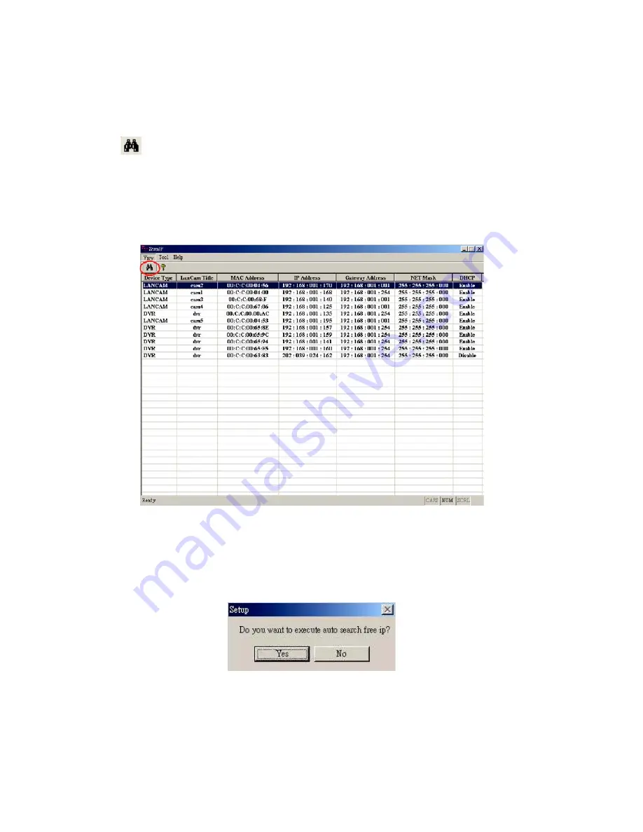
1.  Click the  

  button to discover the connection of the all-type device in the LAN. The 

Device List

 will display the  

  connection of the all-type device.
2.  Select the desired device from the 

Device List

.

3.  Click the desired device to show the window while the LAN CAMERA information acts to display the desired  
  changes instantly.

4.  Do you want to automatically search free IP?
  If and when you want to auto search the free IP, select „Yes” or „No”. If clicked „Yes” the software will provide the  
  „Free IP Address” boxes on the right side of the window. If you click „No”, these address boxes will not show.

Summary of Contents for GLC-1401

Page 1: ...1 Installation and Operating Manual LAN Camera GLC 1401 ...

Page 2: ...onfigure your LAN CAMERA Network Settings 16 5 3 TCP IP Communication Software 17 5 4 TCP IP Installation 18 5 5 TCP IP Configuration Setting 19 5 6 Connection Testing 20 6 Operating Instructions for Image Software and Network 22 6 1 Microsoft Internet Explorer 23 6 2 The LAN CAMERA IP Surveillance 49 7 Advanced Operation 66 8 Specifications 69 9 Function of Client PC 71 10 Dimensional Drawings 71...

Page 3: ...ctions below the cable must be laid in such a way that it is not strained bent or damaged and no moisture can penetrate To prevent fire or shock hazard avoid exposing this unit to rain or moisture Do not block ventilation openings Installation and maintenance of the system may only be carried out by persons with appropriate authorisation for this and in accordance with the installation instruction...

Page 4: ...e also has a built in website server providing many Internet functions and protocols including the MDIX protocol which recognizes both the normal and the crossover cables either of which can connect up with a LAN camera We hope this device makes it easier for you to get your IP address information This unit supports the USB interface which helps you to very easily get an IP address to open the IE ...

Page 5: ...ntrol device This port includes ALARM OUT GROUND ALARM IN and ALARM RECOVER for connecting with external devices WARNING You can t use general RS 232 cables to link up with the I O connectors in the rear panel of the device please see the next page for further details 3 VIDEO OUT Connector The connector provides the unit s composite video signals to a monitor 4 Plug Inlet A 5VDC inlet that connect...

Page 6: ...the pin configuration chart below for details 4 RS 485 D 5 GND Ground contact 6 ALARM RESET INPUT This pin connects to an alarm clear device for clearing an alarm 5V 20mA 0V Active 7 ALARM IN INPUT This is an alarm input that can be programmed in the menu system to active low 5V 20mA 0V Active 8 ALARM OUT OUTPUT This is an alarm output trigger Connect this to external devices such as buzzers or li...

Page 7: ...e switch points down the device can t obtain an IP address from the DHCP server This option is needed to configure the network communication settings 3 3 Flank Panel Right Flank Panel Left Flank Panel 1 2 3 4 CD CONT DRIVE 5 DIP Switch 6 POWER Indicator Indicates the power status of the unit The green light indicates the unit is activating The red light indicates the power is on and the SD card ca...

Page 8: ...tion and ask you what you want to do with your SD card In another words if the user connects the LAN CAMERA with an SD card and the PC via the USB connector the LAN CAMERA can be used as a normal card reader 2 Remove an SD card As a configuring tool Before using the USB configuration setting page please remember to remove the SD card or your PC will read the SD card and won t show this window Netw...

Page 9: ...onitor screen such as the LAN CAMERA factory default Static IP address 192 168 1 168 But the LAN CAMERA Static IP address can only appear if there is a connection between the LAN CAMERA and another device If there is no such connection the LAN CAMERA factory default Static IP address will not appear on the monitor screen 4 1 Connecting with an NVR Use a crossover LAN cable to connect directly to a...

Page 10: ...10 CONNECT TO VIDEO OUT BNC CONNECTOR CONNECT TO DVR VIDEO IN 4 2 Connecting with a DVR TO LAN Camera VIDEO OUT BNC CONNECTOR LAN CAMERA 1 LAN CAMERA 2 LAN CAMERA 16 4 3 Connecting with a Multiplexer ...

Page 11: ... shown on the screen and inform your technical support while ignoring the following steps 10 Power off the LANCAM when this update process is finished then remove the SD card from the LANCAM 11 Reconnect the Ethernet cable to the RJ 45 port if necessary 12 Power ON the LANCAM and it will work normally if the entire update procedure goes correctly 13 Verify the version of the system software WARNIN...

Page 12: ...ort and ignore the following steps 4 Please make sure the function of SD CARD ENABLE is activated in the ALARM and SCHEDULE pages if no cross sign appears beside the SD icon on the screen 5 After recording read the data on the web page of sdget htm If the data cannot be read through the network please read it instead in a PC check the data stored in the LANCAM directory and contact your technical ...

Page 13: ...e at least 5m distant from the camera Open the iris fully and set the lens to the maximum tele position and focus with the focus ring If the lens has automatic iris control select a dark object or use an ND filter 64 x to ensure that the iris is fully open Set the lens to the maximum wide angle position Undo set screw M and turn the C CS ring on the camera until an optimal sharpness is reached Rep...

Page 14: ...acks As the iris is open the depth of focus is very low When shutter times are short this can cause a smear effect bright vertical stripes in light parts of the picture Iris adjustment The working point of the iris should always be above the AGC start and below that of the white clip This range is very small with some cameras making it difficult to adjust the lens It is therefore advisable to swit...

Page 15: ...e to connect directly to a computer CROSSOVER CABLE PIN CONFIGURATION CROSSOVER CABLE TO PC LAN CARD 5 1 2 Connect to a LAN Hub INTRANET The RJ 45 PIN configuration for connecting with a LAN Hub is shown below TO NETWORK TO PC NETWORK CARD HUB Switch Router ...

Page 16: ...for the LAN CAMERA For example there are a range of LAN CAMERA IP addresses from 192 168 1 1 to 192 168 1 255 You can pick one for use from the range of the IP It s not necessary to set MASK and GATEWAY leave the settings as default When a LAN CAMERA is connected to a WAN you must acquire a unique permanent IP address and correctly configure the MASK and GATEWAY settings according to your network ...

Page 17: ...oftware Follow the instructions below to install the TCP IP communication program into your computer Click the Start menu from your computer and point to the Settings Control panel Double click the Network icon to enter the windows ...

Page 18: ...rk components list If the TCP IP is included please process section 4 5 If it is not included please follow section 4 4 to install the TCP IP During the installation you will be requested to insert the Windows CD ROM After installation the PC may be restarted 5 4 TCP IP Installation ...

Page 19: ... DHCP server please select Obtain an IP address automatically Any assigned IP address for the connected LAN CAMERAs must be in the same class type as the server If there is no DHCP server please select specify an IP address and type in the IP address of your PC This IP address must be different from the LAN CAMERA IP but in the same class type NOTE The IP address of a LAN CAMERA in a network must ...

Page 20: ...tions below to ensure whether you have established the connection successfully Click Start Programs MS DOS Prompt Type in ping 192 168 1 168 then Enter See the sample screen below This IP is the LAN CAMERA IP address that is assigned for the connected LAN CAMERA in step 2 ...

Page 21: ...connection If you receive a response as in the sample screen below the connection hasn t been successfully established Please re check all the hardware and software installation by repeating steps 1 to 5 If you still can t establish the connection after re checking please contact your dealer ...

Page 22: ...98 NT 2000 and XP XP if installed with virtual machine 4MB VGA card capable of 24 bit true color display 20MB free hard disk space for software installation 10 100 Base TX network for LAN operation The Microsoft Internet Explorer 5 above Wire Type Cat 5 Connector Type RJ 45 Max Cable Length 100m Switch Hub Wiring Configuration Straight Through PC Wiring Configuration Cross Over RJ 45 PIN configura...

Page 23: ...aces 6 Click the OK button to set your entries and automatically exit the page NOTE The default User Name and Password are admin and 9999 respectively NOTE The page headlined Enter Network Password is shown below Please enter the user name and password of the LAN CAMERA when you see it If either the user name or the password is incorrect please check the input data and rectify it if and as necessa...

Page 24: ... Tilt Zoom settings Click the button to change the time date display mode Click the button to switch high low speed network Click the button to play the live audio Click once again to deactivate Click the button to archive AVI videos into your PC Click once again to deactivate In the recording mode there will appear a red twinkling icon in the upper right hand corner of the image The AVI file will...

Page 25: ...2 Adjust the image setting including Device Title Resolution Quality Frame rate MPEG4 mode only Format and Viewer Type MJPEG mode only if necessary 3 Click the Submit button to submit the new image setting 4 Click the Fine Tune button to enter the Image Fine Tune page to set the details of the device including Brightness Saturation and Sense Up Click the Default button to reset all the settings NO...

Page 26: ... VGA or QVGA Quality Scroll to choose the image quality out of a spectrum of qualities ranging from highest high medium and low to lowest In MPEG4 mode you can also set the quality by typing in the value The custom quality value must be in the range between 64 Kbps to 8192 Kbps Frame rate Click the drop down list to choose the frame rates of 15FPS 24FPS or 25FPS Format Click to choose the MJPEG or...

Page 27: ...ss Enter the 4Byte IP Address in the appropriate blank space the value in each box may be anywhere between 0 and 255 Every LAN CAMERA has to own an IP address to be identified on the network Netmask Fill in the 4Byte Subnet Mask in the required blank spaces usually any numbers between 0 and 255 It is used to identify the subnet where the LAN CAMERA is sited Default gateway Type in the 4Byte Gatewa...

Page 28: ...he Submit button to submit the new FTP setting of the recording 4 Click the Home button to return to the home page Description of function keys FTP IP Address Enter the FTP server DOMAIN NAME or IP address in the appropriate blank spaces User Name Fill in the FTP user name in the attached blank space if the data is not provided warning messages will show up Password Type in the FTP password in the...

Page 29: ...ll in the IP address of the SMTP server and set the recipient s e mail address when and as necessary 3 Click the Submit button to submit the new SMTP setting 4 Click the Home button to return to the home page Description of function keys SMTP Server Enter the SMTP server DOMAIN NAME or IP address in the given blank space Email Address The recipient s e mail address Submit Click to submit the new S...

Page 30: ... zones as and when necessary 3 Click the Submit button to submit the new SMTP setting 4 Click the Home button to return to the home page Description of function keys SNTP Server Enter the SNTP server DOMAIN NAME or IP address in the blank space provided Time Zone As we know the globe is divided into various time zones The user must enter his her time zone If this is not done the time given by the ...

Page 31: ...nd DDNS Password in your Email box 4 Type in the DDNS Host Name the DDNS Account and the DDNS Password 5 Click the Submit button to submit the new setting 6 Click the Home button to return to the home page NOTE Please refer to 5 1 8 PPPoE DDNS section for more details Description of function keys Enable DDNS Function Checkmark to activate the function DDSN Type Click to open the list of three DDNS...

Page 32: ...or more details Description of function keys PPPoE mode Click your choices to enable the PPPoE function Account Enter it in the given space Password Enter it in the required space Submit Click to set Change the Network Setting PPPoE The Network page has on its upper left the PPPoE icon Please follow the steps below to change the PPPoE setting through the network if necessary 1 Click the PPPoE butt...

Page 33: ...d Synchronize With SNTP Server 3 Click the Submit button to submit the new Date and Time setting 4 Click the Home button to return to the home page Description of function keys Current Camera Time Shows the current date and time of the LAN CAMERA Set Manually Manually sets the date and time of the LAN CAMERA Synchronize With Computer Time Synchronizes with the linking computer Synchronize With SNT...

Page 34: ... 6 Enter the Timestamp Format you have chosen 7 Click the Submit button to submit the new user s setting 8 Click the Home button to return to the home page Description of function keys Enable Timestamp Checkmark to activate the function Timestamp Color Click to open the list of eight color modes to choose from BLACK WHITE RED ORANGE YELLOW GREEN BLUE and PURPLE Timestamp Location Click to open the...

Page 35: ...ser s name which will be added or modified Password Enter the new password of the user s name above Confirm Type in the password again for verification Authority Choose an authority option of the user s name from Admin Operator and Viewer Submit Click to submit the new setting to the LAN CAMERA Change the System Setting Users Please follow the steps below to change add the users authority through ...

Page 36: ...er the SYSTEM DIGITAL I O SETTING page 2 Mark Digital Input ON or OFF and the Digital Output ON or OFF Click your choices to enable 3 Click the Submit button to submit the new user s setting 4 Click the Home button to return to the home page Description of function keys Digital Input Select ON or OFF to use the GPIO connector or shut it down Digital Output Select ON or OFF to use the GPIO connecto...

Page 37: ...N or OFF and type in your desired audio volume level from a range of 0 to 11 3 Click the Submit button to submit the new user s setting 4 Click the Home button to return to the home page NOTE This setting is for turning the audio mechanism of the Camera on off automatically The Live audio service is not provided in the MPEG4 mode via the Web browser Description of function keys Audio Mechanism Sel...

Page 38: ... upper left above to enter the Event Log page 2 Choose one of the three buttons shown on the page to view an event when necessary The three buttons are titled First Page Previous 20 and Next 20 Description of function keys First Page Displays the first page Previous 20 Displays the previous 20 pages Next 20 Displays the next 20 pages ...

Page 39: ...pplication Setting page default 2 For storage setting type in the respective required numbers of images you wish to set in the Pre Alarm Memory Buffer and the Alarm Memory Buffer in their corresponding blank spaces 3 Enter the Upload Rate you have chosen 4 Click Submit after each of the above entries for their setting 5 Click the Home button to return to the home page Description of function keys ...

Page 40: ... 3 If it s MJPEG you want fill in the Max MJPEG Numbers entry 4 If AVI is your choice enter its recording rate and duration in seconds and click Submit for their setting Description of function keys MJPEG Format One image per file Max MJPEG Numbers Sets the number of file sequences you can save per second AVI Format audio setting Unlike a single image file this option offers a selected section of ...

Page 41: ... SMTP button on the left side to enter the SMTP Application Setting page 2 Enter the attached file number as and when necessary The maximum number which can be used is 8 3 Click the Submit button to submit the new SMTP setting of the recording 4 Click the Home button to return to the home page Description of function keys File numbers Sets the quantity of images per Email ...

Page 42: ...mode 2 Click Enable Record UPLOAD Via FTP to checkmark the attached box and activate the function MJPEG mode only 3 Click Enable Record Save Into SD card to checkmark the attached box and activate the function 4 Click the Submit button to submit the new setting of the recording 5 Click the Home button to return to the home page Description of function keys Enable Record Upload Via FTP Activates or...

Page 43: ...setting Description of function keys Schedule Check uncheck the first seven boxes in a vertical row on the left to enable disable the programmed scheduled recording function if necessary Vary any of the schedules of the recording setting if necessary please refer to the above description Chart Schedule list Submit Click to submit the new setting to the LAN CAMERA Remove All Schedules Click to clea...

Page 44: ... the home page Description of function keys Enable Alarm Upload via FTP Activates or deactivates the alarm recording upload to the FTP Enable Alarm Save Into SD Card Activates or deactivates the alarm recording to be saved to the CF Card Enable Alarm Upload via SMTP Activates or deactivates the alalrm recording upload to the SMTP Alarm Duration Predetermines the length of the alarm Change the Appl...

Page 45: ...right mouse button to see the popup menu After setting the target zone please click Save setting 4 Enables disables the motion detection function 5 Set up the sensitivity 6 Click the Submit button to submit the new setting of the recording 7 Click the Home button to return to the home page Description of function keys The targeted zone Click and drag the mouse across the targeted zone to draw a re...

Page 46: ...desired file to display the images therein 3 Every file can be deleted by clicking the attached DELETE hyperlink NOTE You can t directly click the hyperlink of the file in the FILELIST of MEMORY CARD page with the right button of the mouse focus then click SAVE to save the file CAUTION If you wish to save the SD CARD files from a camera to your computer you can enter the JPEG column in the FILELIS...

Page 47: ...icked to view the particular corresponding angle of the position in which it is set 4 Select the connecting port The RS 232 communication port functions as a connector to an external control device The RS 485 communication ports function as connectors when two or more units are serially connected to an external control device 5 Upon the buttons being clicked a camera will move one short step only ...

Page 48: ...Name admin and Password 9999 Click OK 2 Choose PPPoE PPPoE mode Select ON Type in Account Type in Password Submit Unplug the power connection 3 Plug in the LAN CAMERA and it will receive an IP address from the ISP dealer this IP address is dynamic every time you unplug and plug in again you ll get a new IP address Test Go to the Internet 1 Set your PC to enter the Internet 2 Desktop IE browser Typ...

Page 49: ...osoft Internet Explorer 6 above In the multi channel recording mode the HD data transfer rates must be 66MB or above 100MB or higher recommended 6 2 1 Introduction to IP surveillance The IP surveillance allows you to access many units of the LAN CAMERA from a remote desktop or a laptop in a TCP IP networking environment It can perform the following functions View live images from the LAN CAMERA St...

Page 50: ...to open up the program selection page as shown below Click the IP surveillance tag to start the LanCam IP surveillance program Install the IP surveillance for the ZIP file 1 Save the ZIP file to your PC and extract the file to a designated directory 2 Open the extracted folder The folder contains 1 file 3 Click on the icon to execute the installation and then follow the on screen instructions to p...

Page 51: ...lick the OK button and enter the console page of the IP surveillance both the user name and password must be entered correctly Click the Cancel button and exit the login of the Network Viewer View the LAN CAMERA video from a remote PC Follow the instructions below to use the IP surveillance to browse a LAN CAMERA video from a remote location Upon entering the IP surveillance a connection box will ...

Page 52: ...o discover the connection of the LAN CAMERA type device in the LAN Instantly the Search Lan Camera page will appear Click the device of your choice and click Select at the bottom of the page to access the Connect Lan Camera Wizard page again 2 Type in the IP Address or the domain name and HTTP port of the device and add the device to the Device List 5 Type in the Password in the Connect Lan Camera...

Page 53: ...izard page NOTE Please click the icon to see the details of the Connect Mode 7 After finishing the setting of the Device Recording please click the Finish button to establish the connection between the device and the computer 8 Click the devise title to begin viewing images with this camera from the Device List NOTE To add more connections or units to the LAN CAMERA please repeat the above instruc...

Page 54: ...to locate the video 2 The Split Screen display function bar This allows you to display the connected device in the single channel and multi format screens 3 The Circle configuring button Click this button to see the following channels 4 The Group Circle button Click this button to change the different group of display 5 The Full Screen button Click this button to show the full screen for surveilla...

Page 55: ...10 Common icons Play Audio Click the button to play the live audio Click once again to deactivate Record Click the button to archive AVI videos into your PC Click once again to deactivate In the recording mode there will appear a red twinkling icon in the upper right hand corner of the image Capture Print Provides the image capturing and printing functions Delete Drop the view here to delete it De...

Page 56: ...be marked in pink colour Recording List Live Event Message Click to refresh the recording list Click to search a starting point of an alarm NOTE To view the starting point of an alarm which was recorded please 1 select the recorded event and 2 click the icon then 3 the starting point will show on the display area ...

Page 57: ...llows you to search a recorded video kept in the HDD of the device Enter the MONTH DAY YEAR HOUR MINUTE you wish to search and click to proceed 9 Functions to fit the starting and ending points of an image display when the user wants to transfer a file JPEG Archives images in the JPEG format to save a single picture in every file AVI Archives images in the AVI format to save a sequence of images i...

Page 58: ... device group Click this button and select the group name then press OK to delete the group Add a new camera For more details please refer to section 6 2 3 page 51 Remove a camera Click this button and select the group name and Lan camera then OK to delete the device To edit camera Please select a device then click this button to edit the device Device setting Provides four pages of setting ...

Page 59: ...ur displays you can click the Device Setting button opening a Device Setting screen set the settings of the Device page where you can change the Audio Mechanism function to OFF Turning it OFF will save the bandwidth from wastage and improve the image display 3 Alarm Setting page 4 SD card Setting page NOTE Please remember to click the Apply button to save the settings Provides four pages of settin...

Page 60: ...ct the directory 3 Live Event Popup Message Sets the maximum number of the popup messages and the displaying time 4 Buzzer settings Sets the buzzer functions Tick mark the blank space for each device to activate it Recording Settings 1 Recording settings You can control the HDD reserved space by using the scroll bar 2 Recording quota setting Set the maximum recording quota of each channel ...

Page 61: ...s to adjust the setting Add the selected period schedule You can also hold down the left mouse button to drag a period Erase the selected period schedule You can also use the right mouse button to cancel the period 4 Select the recording mode 5 Press to show the scheduled recording list 6 Set the secondary schedule Activate or inactivate the other recording modes besides the primary schedule 7 Opt...

Page 62: ...e devices titles and the channels display modes 4 Display area Click the title of the camera and you will see the live image in this area 5 Device Recording Click the Start Record button to start the recording mode and click the Config Record button to set the details of the recording below 6 You can interchange between two buttons here the Device Panel and Web page buttons ...

Page 63: ...e button to lock the operation of this software and the IP Surveillance monitor will be minimized into the systray of the Windows taskbar To unlock the command please click the button once then type in the correct password The Microsoft Windows systray is a portion of the Windows 95 Windows 98 Windows ME Windows NT Windows 2000 and Windows XP Operating Systems that helps display running programs T...

Page 64: ...login to the software You can also change the password by clicking the Tools and Change password items on the list Enter the old password once and the new password twice then press the OK button to save it Tray Press the button to minimize the IP Surveillance monitor into the systray of the Windows taskbar Click the button once to back to the IP surveillance software Exit Setting Press the button ...

Page 65: ...otects an archived image from reproduction or interpolation If an image isn t in the original format made by a LAN CAMERA the Image Viewer will not display the image and instead will send a warning message Not Correct Image right away Close this message to enable you to see the image now 1 Pop up the START menu in your computer and point to Programs IP surveillance to open up the program selection...

Page 66: ... function 5 Set up the sensitivity level from Lowest Low Medium and High to Highest 6 Click the Submit button to submit the setting Recording the images into an SD card while the motion detection function is working 1 Click the Application button in the home page 2 Click the Enable button below the ALARM item on the left side of the page to enter the ALARM APPLICATION ENABLE SETTING page 3 Tick on...

Page 67: ...r the Account and the Password which are provided from your ISP 5 Click the Submit button to submit the setting NOTE Please refer to section 5 1 8 for more details Use the Sub Hostname to view the LANCAM 1 Click the URL block at the top of the PC screen 2 Type in the DDNS Host Name of the LANCAM into the URL block and press the Enter button to enter the login page 3 Enter the user name and fill in...

Page 68: ...setting page 1 Click the System button in the home page 2 Click the Users button on the left side of the page to enter the SYSTEM USERS page Add a new user 1 Please enter the user name the password the confirmed password and choose the authority There are three different levels of authorities namely Admin Operator and Viewer Admin The user who accesses with the admin name and password has the full...

Page 69: ...tivity Detection Integrated motion detector 96 zones 5 levels sensitivity MJPEG Lens Mount C CS Usable Iris Controls Manual DC controlled iris Secondary Storage Via SD card Recording On PC with Viewer Software or on SD Card on camera side Video Output 1Vp p CVBS 75ohms BNC Compression Standard MJPEG or MPEG4 Frame Rate 25 frames sec max recording mode picture size 4 64KB MJPEG Transmission Rate 30...

Page 70: ...Beige Grey 76011 ZELARIS_AC S Surveillance Software for Network Cameras from Eneo Axis 76012 ZELARIS_AC C Client Software for Zelaris_AC S 76023 ZELARIS_AC SMO Site Map Option for Zelaris_AC S 76001 ZELARIS V08 Digital Video Network Crosslink 8 Inputs not Extentable USB 2 0 Dongle 76002 ZELARIS V16 Digital Video Network Crosslink 16 Inputs not Extentable USB 2 0 Dongle 76003 ZELARIS VC Video Clien...

Page 71: ...x 16 Split Real Time REC Capture Audio Live Event Full Screen Playback Viewer Playback Time live event Search Export JPEG AVI Settings Device System Camera management web page Multi camera link Max 16 cameras 9 Function of Client PC 10 Dimensional Drawings Dimensions mm 62 50 95 ...

Page 72: ...n of the all type device 2 Select the desired device from the Device List 3 Click the desired device to show the window while the LAN CAMERA information acts to display the desired changes instantly 4 Do you want to automatically search free IP If and when you want to auto search the free IP select Yes or No If clicked Yes the software will provide the Free IP Address boxes on the right side of th...

Page 73: ... the right Manual insertion of Free IP Address If you have clicked No please manually type in insertions as required in the Free IP Address Gateway Address and NET Mask Follow each insertion you make by typing in the Login Name and Password and click UPDATE to send your alterations to the LAN Camera ...

Page 74: ...ss box on the right to enter it into an IP Address on the left 3 To change any IP address type in the new address in the Free IP Address box on the right as well as the device Login Name and Password in their respective blanks at bottom left then click UPDATE and the new address will automatically be sent to the device ...

Page 75: ...ss of this device is Now LANCam supports the UPnP Universal Plug and Play protocol which makes it easier for you to examine it however it is a pity that Microsoft Windows XP doesn t start this service by default Therefore the following procedures will help you to turn it on and discover your LANCam step by step as shown below ...

Page 76: ...k of 255 255 255 0 There won t be any communication due to different IP class domains and you have to modify the relative settings or the UPnP protocol won t work however checking your own IP address is necessary Here are the procedures to check and modify them Step 1 From the Start menu point to Settings and then click Control Panel Step 2 When Control Panel appears double click the Network Conne...

Page 77: ...77 Step 3 Click the Properties tab in the Network Connections dialog box Step 4 When the Local Area Connection Properties dialog box shows up choose Internet Protocol TCP IP and click Properties ...

Page 78: ...Properties dialog box choose Use the following IP Address to indicate that you do not wish to use DHCP and assign IP Address 192 168 1 200 with Subnet mask 255 255 255 0 Click OK when you finish it Step 6 Choose Close to finish the modification ...

Page 79: ...ult however we have to install some packets before we initialize it The following steps will help you to install them Step1 From the Start menu point to Set Program Access and Default and then click it Step 2 When the Add or Remove Programs dialog box appears click the Add Remove Windows Components button ...

Page 80: ...80 Step 3 Check the Network Services in the Windows Component Wizard dialog box and then click Details Step 4 Check UPnP User Interface and choose OK ...

Page 81: ...81 Step 5 When the original Network Component Wizard dialog box returns click Next Step 6 After about one minute the UPnP installation will be done and choose Finish to close it ...

Page 82: ...ces to start the UPnP protocol The following procedures will teach you how to do it Step 1 From the Start menu point to Settings and then click Control Panel Step 2 When Control Panel appears double click the Administrative Tools icon The Administrative Tools dialog box appears ...

Page 83: ...83 Step 3 Click the Services icon in the Administrative Tools dialog box Step 4 When the Services dialog box shows up double click the SSDP Discovery Service icon ...

Page 84: ...84 Step 5 Choose Automatic in the Startup type and click OK to start it Step 6 When the Services dialog box appears again double click the Universal Plug and Play Device Host icon ...

Page 85: ...LANCams through My Network Place After your installation and starting services the UPnP protocol will take effect You can scan all LANCams in My Network Place like below Just double click the UPnP MPEG4 LANCam icon and the video live stream will pop up automatically without assig ning any IP address in Microsoft Internet Explorer ...

Page 86: ...ws or MS DOS The user can open the PC s MS DOS windows from the WINDOWS 98 operation system or open the PC s Command Prompt windows from either the WINDOWS 2000 or the WINDOWS XP operation system Start a DOS prompt window Type the following in 30 seconds after the booting arp s IP address Ethernet address or arp s IP address MAC address ping IP address Example arp s 192 168 1 100 00 0C 0C 00 00 01...

Page 87: ...ering for a DDNS Enter the URL www dyndns com In the upper right hand corner of the main page where there is an item Sign Up Now as shown below Create an account After clicking Sign Up Now you will enter the Create Account page Please complete the form at the bottom of the page to create your account You will receive an e mail containing instructions to activate your account If you do not follow t...

Page 88: ...reating the account successfully please enter your user name and password in the upper right hand corner of the main page to login as shown below After you login successfully a text will appear saying My Services as shown below ...

Page 89: ...sts item as shown below Click Add Host Service and its 5 service items will appear The Add Dynamic DNS Host item helps to add a new DDNS as shown below Each member may have only one free account and one free account can have only five DDNS Click Add Dynamic DNS Host to enter the DDNS setting page as shown below ...

Page 90: ...stname as s he likes from the right hand side of the Hostname s drop down list NOTE You don t have to set the IP Address in the same format as the LANCAM s IP Address It will renew the IP Address automatically After finishing the setting please press the Add Host button as shown below ...

Page 91: ... 0 25 QVGA 0 66 0 56 0 44 0 38 0 22 ZOOM 2 3 2 5 2 1 5 1 ZOOM 3 3 2 5 2 1 5 1 ZOOM 4 3 2 5 2 1 5 1 2 When frame rate is lower or equal to 15 frames second Highest High Medium Low Lowest FULL D1 2 25 1 94 1 5 1 13 0 75 VGA 1 94 1 69 1 31 0 98 0 66 Half D1 1 13 0 94 0 75 0 56 0 38 Half VGA 0 98 0 84 0 66 0 49 0 33 CIF 0 56 0 47 0 44 0 28 0 19 QVGA 0 5 0 44 0 34 0 25 0 19 ZOOM 2 2 25 1 88 1 5 1 125 0...

Page 92: ...on of Motion Detection but it doesn t seem to work A Check if Motion range and Sensitivity have been set before activating the function 4 My AVI files recorded in the SD Card cannot be displayed What can I do to display the files A Please visit http www morgan multimedia com to download Morgan M JPEG codec and install it and then check the selection of the IJP Core 5 How to turn on off the OSD on ...

Page 93: ... VHM LAN02 VHM LAN03 and VHM LAN04 A0 N blue C0 L1 black B0 PE green yellow B2 Video Inner conductor B3 Video GND A1 LAN orange white Pin 1 A2 LAN orange Pin 2 A3 LAN green white Pin 3 A4 LAN blue Pin 4 A5 LAN blue white Pin 5 A6 LAN green Pin 6 A7 LAN brown white Pin 7 A8 LAN brown Pin 8 ...

Page 94: ... Exclusive distribution through specialised trade channels only VIDEOR TECHNICAL E Hartig GmbH Carl Zeiss Straße 8 63322 Rödermark Germany Tel 49 0 6074 888 0 Fax 49 0 6074 888 100 www videortechnical com Technical changes reserved Copyright by VIDEOR TECHNICAL 07 2008 ...

Reviews: