background image

Proline Prowirl 72F, 72W, 73F, 73W

Hauser

13

Operating conditions: installation

Installation instructions

Vortex meters require a fully developed flow profile as a prerequisite for correct volume flow measurement. 
For this reason, please note the following points when installing the device:

Orientation

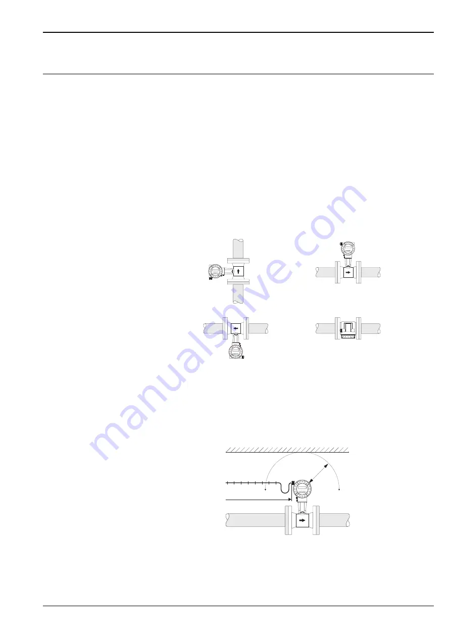
The device can generally be installed in any position in the piping. 
In the case of liquids, there should be upward flow in vertical pipes to avoid partial pipe filling (see orientation 
A). 
In the case of hot media (e.g. steam or fluid temperature 

 200 °C), select orientation C or D so that the 

permitted ambient temperature of the electronics is not exceeded. Orientations B and D are recommended for 
very cold media (e.g. liquid nitrogen).
Orientations B, C and D are possible with horizontal installation.
The arrow indicated on the device must always point in the direction of flow in all orientations. 

Caution! 
• If fluid temperature is 

 200 °C, orientation B is not permitted for the wafer version 

(Prowirl 72W, 73W) with a nominal diameter of DN 100 and DN 150.

• To guarantee the flow measurement of liquids, the measuring tube must always be completely full in pipes 

with vertical downward flow.

A0001869

Minimum spacing and cable length

To ensure problem-free access to the measuring device for service purposes, we recommend you observe the 
following dimensions:

• Minimum spacing in all directions = 100 mm (A)
• Necessary cable length L + 150 mm

A0001870

Rotating the electronics housing and the display

The electronics housing can be rotated continuously 360 ° on the housing support. The display unit can be 
rotated in 45 ° stages. This means you can read off the display comfortably in all orientations.

B

D

A

C

L

A

Summary of Contents for Proline Prowirl 72F

Page 1: ...l systems HART PROFIBUS PA FOUNDATION Fieldbus Relevant safety aspects Pressure Equipment Directive Up to SIL 2 Your benefits The robust Prowirl sensor tried and tested in over 100 000 applications of...

Page 2: ...rating conditions installation 13 Installation instructions 13 Inlet and outlet run 15 Operating conditions environment 17 Ambient temperature range 17 Storage temperature 17 Degree of protection 17 V...

Page 3: ...tional to the volume flow A0003938 The K factor is used as the proportional constant A0003939 EN Within the application limits of the device the K factor only depends on the geometry of the device It...

Page 4: ...which is located in the paddle of the DSC sensor i e directly in the fluid Fig Pt 1000 Flow computer Prowirl 73 The electronics of the measuring device have an integral flow computer With the aid of t...

Page 5: ...example The measured process variables volume flow temperature or the calculated process variables mass flow heat flow or corrected volume flow can be output as the output variables Measuring range Th...

Page 6: ...erally be output If configured the calculated measured variables density specific enthalpy saturation steam pressure for saturated steam Z factor and flow velocity can also be shown on the local displ...

Page 7: ...OFIBUS PA in accordance with EN 50170 Volume 2 IEC 61158 2 MBP galvanically isolated Current consumption 16 mA Error current FDE Fault Disconnection Electronic 0 mA Data transmission rate supported ba...

Page 8: ...ult Disconnection Electronic 0 mA Data transmission rate supported baudrate 31 25 kBit s Signal encoding Manchester II Function blocks 4 x Analog Input 2 x totalizer Output data volume flow mass flow...

Page 9: ...Ex 12 36 V DC Ex d 15 36 V DC Ex i and Ex n 12 30 V DC UKl Terminal voltage non Ex min 12 V DC Ex d min 15 V DC Ex i and Ex n min 12 V DC Imax Output current 22 6 mA Low flow cut off Switch points for...

Page 10: ...ant for remote version D Only Prowirl 72 PFM pulse frequency modulation wiring Wiring when using the HART input Process for reading in pressure temperature or density with Prowirl 73 A0004215 A Proces...

Page 11: ...7100 Terminal number 1 white 2 brown 3 green 4 yellow 5 gray 6 pink 7 blue 8 red Supply voltage HART Non Ex 12 36 V DC 18 36 V DC Ex i and Ex n 12 30 V DC 18 30 V DC Ex d 15 36 V DC 21 36 V DC PROFIBU...

Page 12: ...s 2 3 o f s for remote version for Re between 4 000 20 000 Mass flow other media depending on the pressure value specified in the instrument functions and the chosen fluid individual error observation...

Page 13: ...s B C and D are possible with horizontal installation The arrow indicated on the device must always point in the direction of flow in all orientations Caution If fluid temperature is 200 C orientation...

Page 14: ...rmitted is illustrated in the diagrams These apply equally to both the compact version and the sensor in the remote version A0001868 1 Flanged version 2 Wafer version Wafer version mounting set The ce...

Page 15: ...ecially designed perforated plate flow conditioner can be installed if it is not possible to observe the inlet runs required Page 16 Outlet runs with pressure and temperature measuring points If press...

Page 16: ...les of pressure loss for flow conditioner Installation of delta heat measurement Prowirl 73 HART The second temperature measurement takes place by means of a separate sensor and is read in via HART Pr...

Page 17: ...on dust ignition proof 20 55 C Degree of protection IP 67 NEMA 4X in accordance with EN 60529 Vibration resistance Acceleration up to 1 g 10 500 Hz following IEC 60068 2 6 Electromagnetic compatibilit...

Page 18: ...stainless steel ANSI B16 5 Class 150 300 Prowirl 72W and 72F Class 600 1500 Prowirl 72F A0003402 200 100 0 20 40 60 80 100 120 140 160 0 100 200 300 400 C bar PN 63 250 200 100 0 5 10 15 20 25 30 35 4...

Page 19: ...opment A0001922 JIS B2238 10 20K Prowirl 72W and 72F 40K Prowirl 72F Butt weld version PN250 Cl 1500 Prowirl 72F 200 100 170 190 200 210 220 230 240 250 260 0 100 200 300 400 C bar JIS 10 40 K 200 100...

Page 20: ...the Internet www applicator com and on a CD ROM for local PC installation Mechanical construction Design dimensions Dimensions of transmitter remote version A0003594 The following dimensions differ de...

Page 21: ...version and for the version with a DSC sensor made of Alloy C 22 and for Prowirl 73 version with extended temperature range The weight data refer to the compact version The weight increases by 0 5 kg...

Page 22: ...Standard Ex i and Ex n version the dimension 149 mm changes to 142 mm in the blind version Ex d version the dimension 151 mm changes to 144 mm in the blind version The dimension depends on the cable g...

Page 23: ...00 33 17 PN 1002 53 9 195 0 19 PN 1602 52 3 PN 2501 47 7 200 0 306 288 38 23 Butt weld1 47 7 60 3 306 288 9 80 PN 40 82 5 200 0 283 200 24 20 PN 632 81 7 215 0 323 200 39 24 PN 1002 80 9 230 0 27 PN 1...

Page 24: ...Cl 300 52 6 165 0 22 4 Schedule 80 Cl 150 49 2 152 4 19 1 Cl 300 49 2 165 0 22 4 Cl 6002 49 2 165 1 310 200 33 14 Cl 15001 47 7 215 9 306 344 38 1 30 Butt weld1 47 7 60 3 306 288 9 3 Schedule 40 Cl 1...

Page 25: ...00 18 10 Schedule 80 20K 38 1 140 0 18 40K1 38 1 160 0 303 200 31 14 50 Schedule 40 10K 52 7 155 0 270 200 16 12 20K 52 7 155 0 18 Schedule 80 10K 49 2 155 0 16 20K 49 2 155 0 18 40K1 49 2 165 0 310 2...

Page 26: ...0 3 Prowirl 73F only PN 160 A0003600 A Standard Ex i and Ex n version B Remote version C Ex d version transmitter The following dimensions change as follows in the blind version without local operatio...

Page 27: ...0 89 PN 100 154 1 355 0 91 PN 160 146 3 355 0 Prowirl 72F Dualsens version to ANSI B16 5 DN Pressure rating d D H L X Weight ANSI mm mm mm mm mm kg 1 Schedule 40 Cl 150 40 9 127 0 303 200 31 16 Cl 300...

Page 28: ...52 7 155 0 310 200 33 18 20K 52 7 155 0 Schedule 80 10K 49 2 155 0 20K 49 2 155 0 40K 49 2 165 0 80 Schedule 40 10K 78 1 185 0 323 200 39 25 20K 78 1 200 0 Schedule 80 10K 73 7 185 0 20K 73 7 200 0 4...

Page 29: ...1500 and butt weld version only for Prowirl 72 1 4571 316Ti UNS S31635 in conformity with NACE MR0175 and MR0103 Alloy C 22 version only for Prowirl 72 Alloy C 22 2 4602 A 494 CX2MW N 26022 in confor...

Page 30: ...C sensor flange Standard for pressure ratings up to PN 40 Cl 300 JIS 40 K apart from Dualsens version Stainless steel 1 4435 316L in conformity with NACE MR 0175 and MR 0103 Pressure ratings PN 63 160...

Page 31: ...e found in the separate Ex documentation Pressure measuring device approval Devices with a nominal diameter smaller than or equal to DN 25 correspond to Article 3 3 of the EC Directive 97 23 EC Pressu...

Page 32: ...ermination of Supercompressibility Factors for Natural Gas PAR Research Project NX 19 Functional safety Prowirl 72 SIL 2 in accordance with IEC 61508 IEC 61511 1 Prowirl 73 SIL 1 Ordering information...

Page 33: ...20 PROFIBUS PA for data transmission Paperless Recorder Ecograph T for displaying recording and communication of data Documentation Operating Instructions Proline Prowirl 72 Operating Instructions Pro...

Page 34: ...Proline Prowirl 72F 72W 73F 73W 34 Endress Hauser...

Page 35: ...Proline Prowirl 72F 72W 73F 73W Endress Hauser 35...

Page 36: ...al Head Quarter Endress Hauser GmbH Co KG Instruments International Colmarer Str 6 79576 Weil am Rhein Deutschland Tel 49 76 21 9 75 02 Fax 49 76 21 9 75 34 5 www endress com info ii endress com TI070...

Reviews: