background image

Float Gauge LTC2230/LTC2240

12

Hauser

4

Installation Adjustment

4.1

Wave Guard

1.

Use the following specifications for wave guards; 6B, SGP, jointless, and white pipe.

2.

Completely remove burrs from weld joints and from the inside of pipe joints that have been cut and 
rewelded.

3.

Be sure that airtightness is maintained in the flange between wave guard and gauge head.

4.2

LTC Installation

Installation Procedure

1.

Remove the rear cover of gauge head [6].

2.

Hold the measuring wire [2] by hand and remove the fixing sponge [1] (black, Approx, 16 x 16 x 16mm).

3.

Pull on the measuring wire to connect the float [5].

As the float begins to weigh down on the measuring wire (1.2kg), confirm that the float is securely 
connected to the measuring wire before releasing.

4.

Move the crimp sleeve [4] upward and connect the measuring wire to the float.

5.

Move the crimp sleeve downward and crimp the center of the sleeve so that the measuring wire does not 
disconnect from the float.

6.

Hold on to the measuring wire and lower the float slowly into the wave guard.

7.

When the float reaches the bottom of the tank, install the gauge head.

8.

Replace the rear cover.

This completes the installation procedure.

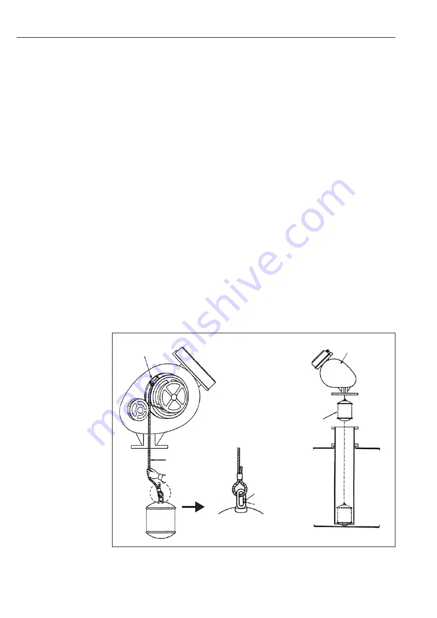
Figure 5:

LTC Gauge Head Installation

Fixing Sponge [1]

Gauge Head [4]

Float [5]

Crimp Sleeve [3]

Crimping Part

Measuring Wire [2]

4 Installation Adjustment

Summary of Contents for LTC2230

Page 1: ...BA01013G 08 EN 01 13 71227305 Operation Instructions Float Gauge LTC2230 LTC2240 ...

Page 2: ... Order Information 6 2 3 Scope of Delivery 8 3 Installation 9 3 1 Incoming Acceptance Transport Storage 9 3 2 Installation Conditions 10 3 3 Standard Installation 12 4 Installation Adjustment 13 4 1 Wave Guard 13 4 2 LTC Installation 13 4 3 Indicator Adjustment 14 5 Maintenance 16 6 Troubleshooting 17 6 1 Spare Parts 17 6 2 Failure Causes and Countermeasures 18 6 3 Return 19 6 4 Disposal 19 6 5 Co...

Page 3: ... make sure that the measuring system is correctly wired according to the wiring diagrams The measuring system must be grounded Observe all law and regulations applicable and valid for your country and pertaining to the opening and repairing of electrical devices 1 3 Operational Safety Caution Changes or modifications not expressly approved by the party responsible for compliance could void the use...

Page 4: ...dentification 2 1 Device Designation 2 1 1 Nameplate The following technical data are given on the instrument nameplate Figure 1 LTC series Nameplate 䐟䚷Order Code 䐠䚷Serial Number 䐡䚷Product Type 䐢䚷Measurement Range 䐣䚷Tag Number if any 2 Identification ...

Page 5: ...sion TSP no to be spec 030 Measuring Range 1 2 5m 2 5m 3 10m 9 Special version TSP no to be spec 040 Display 1 Dial 1 pointer 9 Special version TSP no to be spec 050 Application 000 Gauge head only 081 Standard application 999 Special version TSP no to be spec 060 Float 1 2 1kg d 140mm 0 5 0 93g cm3 2 2 4kg d 140mm 0 94 2 0g cm3 3 Not selected 9 Special version TSP no to be spec 070 Colour 0 Slive...

Page 6: ...o to be spec 030 Measuring Range 1 2 5m 2 5m 3 10m 9 Special version TSP no to be spec 040 Display 1 Dial 1 pointer 9 Special version TSP no to be spec 050 Application 000 Gauge head only 083 Standard application 999 Special version TSP no to be spec 060 Float 1 2 1kg d 140mm 0 5 0 93g cm3 2 2 4kg d 140mm 0 94 2 0g cm3 3 Not selected 9 Special version TSP no to be spec 070 Colour 0 Sliver 9 Specia...

Page 7: ...follow the instructions concerning the unpacking transportation and storage of measuring instruments provided in the chapter 3 1 Incoming Acceptance Transportation Storage The scope of delivery consists of Assembled instrument Accompanying documentation Operating Instructions this manual 2 Identification ...

Page 8: ... missing and that the items match your order 3 1 2 Transportation Follow the safety instructions and conditions of transportation for instruments in excess of 18kg 40 lbs 3 1 3 Storage Pack the measuring instrument so that it is protected against impacts during storage and transportation The original packing material provides the optimum protection for this The allowed storage temperature is 20 to...

Page 9: ...LTC2240 3 2 Installation Conditions 3 2 1 Dimensions of LTC2230 Figure 2 LTC2230 Dimensions Indicator White Black Ø156 Float Density Weight Measured Liquid Specific Density Weight 0 5 to 0 93g cm 2 1kg 0 94 to 2 0g cm 2 4kg 3 Installation ...

Page 10: ...C2240 10 Endress Hauser 3 2 2 LTC2240 Dimensions Figure 3 LTC2240 Dimensions White Black Ø156 Float Density Weight Measured Liquid Specific Density Weight 0 5 to 0 93g cm 2 1kg 0 94 to 2 0g cm 2 4kg Indicator 3 Installation ...

Page 11: ...C2240 3 3 Standard Installation Figure 4 LTC Standard Installation LTC2230 Flange Measuring Wire Float Wave Guard Ventilation Hole Ø20 Tank Height LTC2240 Flange Measuring Wire Float Wave Guard Ventilation Hole Ø20 Tank Height 3 Installation ...

Page 12: ...n the measuring wire to connect the float 5 As the float begins to weigh down on the measuring wire 1 2kg confirm that the float is securely connected to the measuring wire before releasing 4 Move the crimp sleeve 4 upward and connect the measuring wire to the float 5 Move the crimp sleeve downward and crimp the center of the sleeve so that the measuring wire does not disconnect from the float 6 H...

Page 13: ...tain a reliable value measure the liquid level two or three times using a measuring tape which has been officially tested accurate to within 0 3 mm m 1 2mm 10 m Calibrate to the values only after accurate data has been gathered Figure 6 Indicator Adjustment 4 3 2 Calibration through Calculation for Empty Tank 1 When the tank is empty calculate the liquid level Lƒ using the following formula and se...

Page 14: ...he value error difference of submerging float in water and in any liquid other than water density 1g cm3 using the following formula After setting the indicator to the measured value for water determine Lb in the following formula If the value of Lb is a positive integer add that value to the determined indicator value If the value of Lb is a negative integer subtract that value from the determine...

Page 15: ...nstallation environment inside the tank as well as on frequency of use Inspect components according to the following table Inspection Parts Descriptions Conster Wear Remove the dust and other particles on the front surface of the constar Replace the conster if any cracks are discovered Fog or Condensation on Indicator Screen Confirm that indicator cover is securely tightened and that there is no f...

Page 16: ...r LTC series which can be ordered from Endress Hauser are shown with their order numbers in the diagram below Contact Endress Hauser service representatives for further assistance Figure 7 Spare Parts 㻤㻝 㻤㻟 㻤㻟 㻤㻝 㻤㻢 㻥㻠 㻤㻠 㻤㻞 㻥㻞 㻥㻟 㻥㻝 㻤㻣 㻤㻝 㻤㻤 㻤㻡 Without Ring With Ring Oil Seal Bevel Gear 㻤㻡 LTC Developed Figure 6 Troubleshooting ...

Page 17: ...g w o ring 85 56004302 Conster drum 92 56004413 Measuring wire 0 8mm 10m 52015582 Conster spring 5m 56004416 Measuring wire 0 8mm 5m 017860 5033 Conster spring 10m 93 56004405 Lifting ring float 140D 86 56004304 Conster reeling drum 94 56004925 Wire sleeve 0 8mm 87 70106001 Main shaft assembly Symptom Possible Causes Countermeasures Indicator does not move 1 Severed measuring tape 2 Conster broken...

Page 18: ...nally specify An exact description of the application The chemical and physical characteristics of the instrument A short description of the error that occurred specify the error code where possible Operating time of the device Note A copy of the Declaration of Contamination is included at the top of this operating manual Caution Hazardous materials may be attached to damaged parts of LTC or its p...

Page 19: ...Dial 1 Pointer Accuracy 30mm ρ 1g cm3 Maximum Operating Pressure Max 20kPa Measuring Specific Density Range 0 5 to 2 0g cm3 Total Weight LTC2230 8kg LTC2240 8kg Allowable Temperature Range 20 to 60 C Process Connection 10K 150A RF SS400 flange JIS B2220 6 150lbs RF SS400 flange ANSI B16 5 7 Technical Data ...

Page 20: ...____________________ We hereby certify that this declaration is lLLED out truthfully and completely to the best of our knowledge We further certify that the returned parts have been carefully cleaned To the best of our knowledge they are free of any residues in dangerous quantities Wir bestätigen w bestätigen die vorliegende Erklärung nach unserem besten Wissen wahrheitsgetreu und vollständig ausg...

Page 21: ...1013G 08 EN 01 13 71227305 FM XML DITA 11 0 Endress Hauser Japan Co Ltd Product Center Yamanashi 862 1 Mitsukunugi Sakaigawa cho Fuefuki shi Yamanashi 406 0846 Japan Phone 81 55 266 4964 Fax 81 55 266 4969 ...

Reviews: