TMT182
4 Wiring
Hauser
13
4.2.3
HART
®
connection
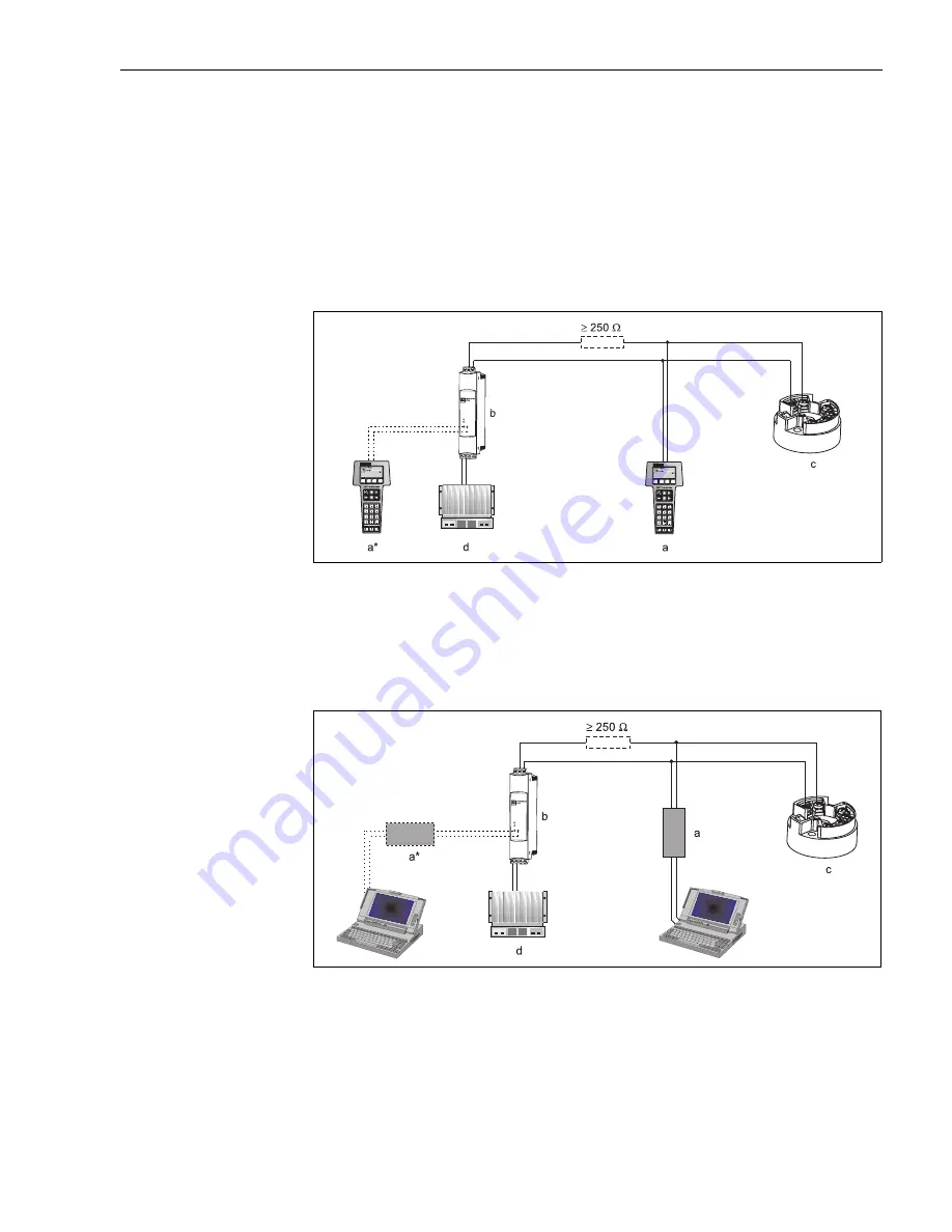
Connection is made directly using the 4 to 20 mA signal cables or the communication sockets fitted
to a power supply or barrier (see fig. 7 and see fig. 8).
In order to connect the transmitter in hazardous area, please read the separate Ex documentation.
!
Note!
The measurement circuit must have a load of at least 250
Ω
. If using the E+H power supplies
RNS221 and RN221N, this resistance is already installed in the unit and is therefore not required
externally (see fig. 7, and see fig. 8)!
Connection of a HART
®
hand operated module DXR275, DXR375
ƒig. 7:
: Electrical connection of the HART
®
operated module
a = HART
®
module, a* = HART
®
module connected to the communication sockets of a power supply, b = Loop power
supply (e.g. RNS221 power supply or RN221N active barrier), c = HART
®
transmitter, d = PLC with passive input
Connection of Commubox FXA191
!
Note!
Set the Commubox DIP switch to ’HART
®
’!
ƒig. 8:
: Electrical connection of the Commubox FXA191
a = Commubox FXA191 (in combination with a PC - E+H operating software ’Commuwin II’), a* = Commubox FXA191
connected to the communication sockets of a power supply unit, b = Loop power supply (e.g. RNS221 power supply or
RN221N active barrier), c = HART
®
transmitter, d = PLC with a passive input
Summary of Contents for iTEMP TMT182
Page 2: ...TMT182 2 Endress Hauser...
Page 35: ...TMT182 Endress Hauser 35...


