


ENDEVCO 6634C
INSTRUCTION MANUAL
IM6634C
Page 2-1
SECTION 2:
UNPACKING AND CHECKOUT
1.
INTRODUCTION
Unpack and check for all items in shipment, install optional boards, and power-up.
The ENDEVCO Model 6634C Vibration Amplifier is normally shipped in a single box containing the Model 6634C with the
ordered X (English/Metric) choices installed. The power cable, mating multi-pin connectors, and manual are also packed
in this box. Option boards are shipped in individual packages. Option boards will be installed in the amplifier if ordered as
a system.
2.
UNPACK
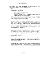
The equipment has been inspected and tested at the factory, and is ready for operation when received. Inspect for
damage during shipment. Carefully open the box and inspect each item for signs of damage. Report any obvious
damage to the carrier, immediately. If the shipping container or cushioning material is damaged, it should be kept until the
contents of the shipment have been checked mechanically and electrically. In any case, save the packing materials for
future shipments of the hardware. Check each item of the shipment against the included packing list. Notify ENDEVCO
of any discrepancy.
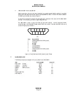
Unwrap the Model 6634C and set on a level, firmly supported surface. The unit contains a built-in power supply. No
cooling fan is required. There is no power switch, and the unit derives its power from the rear power cable connector.
The line voltage selection switch is inside the unit, and should be checked to ensure that it is correctly set.
WARNING: REMOVE POWER CORD FROM UNIT BEFORE OPENING CASE TO PREVENT ELECTRICAL SHOCK.
3.
INSTALL OPTION BOARDS
Optional boards may be installed by the user or at the factory. CARE MUST BE TAKEN when unwrapping and handling
the plug-in cards to avoid electrostatic discharge (ESD) which may damage sensitive components.
WARNING: HANDLE UNWRAPPED CARDS ONLY AFTER GROUNDING YOUR BODY WITH AN ESD DEVICE,
SUCH AS A GROUNDED WRIST STRAP.
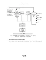
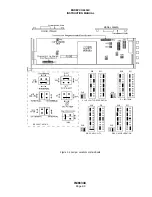
Unpack the option board and unwrap it from its anti-static wrapping. Install the Model 35840A Programmable Six-Pole
Filter Board by plugging board (component side down) into multi-pin connector (P8) located on upper edge of main
board, just behind the power supply module (See Figure 2-4). Install the Model 35843 Serial Interface Board by plugging
board (component side up) into multi-pin connector (P7) located on lower edge of main board, midway between power
supply module and front panel. In either case, secure board by installing the supplied screws into brackets in option board
(two per board). For the Model 35843 board, mount remote RS-232 connector to back panel and route wiring below
power supply module. Observe any instructions provided with Optional Board.
NOTE: External Calibration must be performed after installing Programmable Filter Board to obtain specified accuracy.