


ENDEVCO 6634C
INSTRUCTION MANUAL
IM6634C
Page 3-5
D.
FULL SCALE OUTPUT VOLTAGE
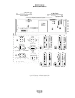
The AC and the DC Full Scale Output Voltages can be independently set to 1V, 5V, and 10 V, by moving internal
jumpers. The W7 jumper on the main board controls the DC Output Voltage selection, and the W5 jumper on the
main board controls the AC Output Voltage selection. The locations of these two jumpers are shown in Figure 2-
4. The shorting clip should be moved to the position corresponding to the desired output F.S. voltage on each
jumper.
5.
PROGRAMMABLE FILTER
An optional programmable filter (Model 35840A) may be used to limit the frequency range of the signal being measured
and output.
The Programmable Six-Pole Filter is available is two configurations. 35840A jumper position provides a low-pass
programming range of 50 Hz to 5,000 Hz or 100 Hz to 10,000 Hz (-3 dB point). (Note: The -5% frequency point can be
obtained by multiplying the Cutoff Frequency by 1.2 for the high pass filter and by 0.833 for the low pass filter.)
At power-up, the filter corner frequencies are set to the default settings which were previously stored in non-volatile
memory. The Digital Readout displays the vibration amplitude corresponding to the DC Output (measured on the signal
amplitude in the pass band) with the decimal point fixed by the output full scale setting.
A.
FILTER IN/OUT
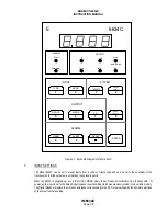
Pressing IN/OUT in the Normal Mode will cause the Digital Readout Indicator to flash the present filter condition
("In" or "Out") of the 6634C. While the filter condition is being indicated, the ALARM and OUTPUT displays are
off. If no filter is installed, the Digital Readout Indicator will flash "Err0", and the only keypress that will be accepted
is ENTER.
To change the present setting, press IN/OUT again. The display will toggle between "in" and Out" each time
IN/OUT is pressed. When the desired choice is displayed, press ENTER. The new filter condition choice is
implemented, and the unit returns to Normal Mode. The unit automatically returns to Normal Mode if no key is
pressed for about 20 seconds. A different filter condition can be selected for each input type (PE, Velocity Coil,
RCC Input) and output mode. The new filter condition choices are stored as the defaults for each input type and
output mode in non-volatile memory.
NOTE: With the filter disabled, the acceleration output frequency response is from 2 Hz to 30 kHz. With the filter
enabled, the acceleration output frequency response will exhibit characteristics of the filter specifications.
B.
CUTOFF FREQUENCIES
Pressing UPPER CUTOFF or LOWER CUTOFF in the Normal Mode will cause the Digital Readout Indicator to
flash the present corresponding (upper or lower) filter cutoff frequency of the 6634C. While the cutoff frequency is
being indicated, the ALARM and OUTPUT displays are off. If no filter is installed, the Digital Readout Indicator will
flash "Err0", and the only keypress that will be accepted is ENTER.
To change the present setting, type in the desired Filter Cutoff using the numeric keys. The display will flash the
numbers entered. If an illegal value is entered, the display flashes ERR1, indicating that a new value should be
reentered. When the desired entry is displayed, press ENTER. The new cutoff frequency is implemented, and
the unit returns to Normal Mode. The unit automatically returns to Normal Mode if no key is pressed for about 20
seconds. Different cutoff frequencies can be selected for each input type/output mode combination. The new
cutoff frequency settings are stored as the defaults for each input type/output mode combination in non-volatile
memory.