


ENDEVCO 6634C
INSTRUCTION MANUAL
IM6634C
Page 2-4
C.
REMOTE MODE
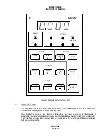
In the REMOTE mode, the front panel continuously displays the RS-232 address, Adnn, where nn is the address
of the unit. In the Remote Mode, any of the settings can be programmed by sending commands over the RS-232
bus to the Model 6634C. The same checks which were made in the previous paragraphs can be performed over
the RS-232 bus. This technique will be covered in Section 4 of this manual.
Connect the computer/controller to the Model 6634C via the RS-232 bus as follows. Turn off the power to both
the controller and the 6634C. Attach the interconnect cable to the RS-232 connector at the computer/controller
and to the RS-232 connector on the rear panel of the 6634C. Tie the LOCAL/REMOTE pins on the serial
interface connector together. If more than one Model 6634C is used, connect all the RS-232 Transmit pins (on
the 6634C’s) to the computer/controller Receive pin. Connect all the RS-232 Receive pins (on the 6634C’s to the
computer/ controller Transmit pin.
No two 6634C’s can have the same RS-232 address (except Ø, see below). The address of each 6634C can be
set from the front panel (in Local mode). Press <ENTER> then <3>. The front panel displays Adnn, where nn is
the present address of the unit. Input the new desired address, from 1 to 16, and press <ENTER>. Unit returns
to normal mode with new address installed. Address Ø disables REMOTE operation. Address Ø is the factory-set
address for the Model 6634C.
Up to 16 Model 6634C units can be daisy-chained with a single computer/controller. All 6634C can receive
commands simultaneously from controller, but only one (at a time) can be made Listener/Talker (see Section 4,
Operation with RS-232 Interface).
7.
CONNECTIONS
Operating conditions and input/output connections.
The ENDEVCO Model 6634C Vibration Amplifier may be located in a normal laboratory operating environment. Specified
performance is obtained over the following limits:
Temperature:
+41 to 122°F (+5 to 50°C)
Humidity: 0 to 95% relative humidity
A.
PREPARE CONNECTIONS
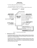
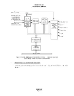
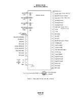
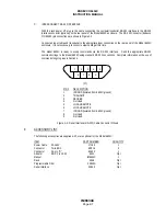
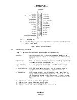
The input connections to the Model 6634C are standard BNC coaxial and Endevco P/N EP316 differential
connectors. The output connections from the Model 6634C are standard 25-socket, "D" connectors (Endevco
P/N EJ370). Wiring diagrams for these connectors are shown in Figure 2-1 and 2-3.
B.
SYSTEM CALIBRATION
Calibration is performed at ENDEVCO on each Model 6634C. For a pre-operational checkout and unit
calibration, perform the following System Calibration:
For a calibration of each 6634C channel, pulse the /SYS-CAL input (TTL digital discrete input, or ground /SYS-
CAL) low for at least 100 milliseconds while applying a 5.000V pk, 300.0 Hz sinewave signal at the EXT-CAL input
(and at the VEL COIL/RCC input, if velocity coil or RCC input requires calibration). Allow 3 minutes for the test to
be completed. As the Calibration process proceeds, the Cal Status is shown on the front panel display as follows:
adjusting the dc offset (CAL1), adjusting the full scale output and the integrators (CAL2), adjusting the input
sensitivities (CAL3), adjusting the filter cutoffs (CAL 4, if filter is installed). Failure of Calibration is signaled by
displayed error messages.