background image


TSD012                                                                                                 SIGNALPOINT I/O UNIT, ISSUE 1 – 09/09/13 


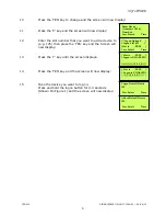
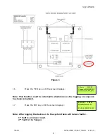
(To clear the faults press Silence Alarms button and then the Reset/LED Test 

button until the faults have cleared)   


18


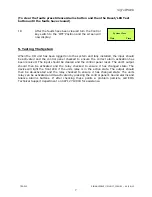
After the faults have been cleared turn the Control 

key switch to the ‘OFF’ Position and the screen will 

now display: 


5. Testing The System 


When the I/O unit has been logged onto the system and fully installed, the input should 

be activated and the control panel checked to ensure the correct alarm activation has 

been received. The input should be cleared and the control panel reset. The unit’s output 

should then be activated and the relay checked to ensure it has changed state. The 

device will light the front LED if the units relay is in the active state. The output should 

then be de-activated and the relay checked to ensure it has changed state. The units 

relay can be activated and de-activated by pressing the control panel’s Sound alarms and 

Silence Alarms buttons. If after checking these points a problem persists, call EMS 

Technical Support department on 08712 710804 for assistance. 


       System Clear 
 
 Date       

Time


Summary of Contents for Signal point

Page 1: ...INPUT OUTPUT UNIT INSTALLATION MANUAL ...

Page 2: ...D012 SIGNALPOINT I O UNIT ISSUE 1 09 09 13 2 Table of Contents Section Page No 1 INTRODUCTION 3 2 I O UNIT POSITIONING 3 3 INSTALLATION 3 4 INPUT OUTPUT UNIT LOGGING ON PROCEDURE 4 5 TESTING THE SYSTEM 7 ...

Page 3: ...radiators and air conditioning ducts will also adversely affect the performance of the system if they are too near the device 3 Installation The I O unit is a battery powered device therefore no power wiring is necessary The units input and output connection details are shown in the attached diagram Figure 1 An installation drawing is also supplied P04242 The following paragraphs outline the insta...

Page 4: ... display 2 Press the 0 key and the screen will now display 3 Press the key until the screen displays 4 Press the YES key and the screen will now display 5 Press the key until the screen displays 6 Press the YES key and the screen will now display 7 Enter 221100 then press the YES key and the screen will display 8 Press the key until the screen displays 9 Press the YES key and the screen will now d...

Page 5: ... 13 Press the key until the screen displays 14 Press the YES key and the screen will now display 15 Take the device you want to log on Press and hold the logon button for 2 3 seconds Shown On Figure 1 and the screen will now display Enter Device Numbers 1 256 Number Yes Finish Time Logon Options Logon Slot 125 Slot is FREE Yes Select Time Slot is FREE Logon is DISABLED Slot is FREE Logon is ENABLE...

Page 6: ...ed to disabled once the logging on sequence has been completed 17 Press the NO key until the screen displays Note After logging the device on to the system there will be two faults 1st fault is processor reset 2nd fault is the Tamper Slot is IN USE Logon is DISABLED 01 FAULT TOT 02 Default Device 125 ZONE 01 DEVICE 125 Figure 1 ...

Page 7: ...ure the correct alarm activation has been received The input should be cleared and the control panel reset The unit s output should then be activated and the relay checked to ensure it has changed state The device will light the front LED if the units relay is in the active state The output should then be de activated and the relay checked to ensure it has changed state The units relay can be acti...

Page 8: ...oup co uk Dealer Information The information contained within this literature is correct at time of publishing The EMS Group reserves the right to change any information regarding products as part of its continual development enhancing new technology and reliability The EMS Group advises that any product literature issue numbers are checked with its head office prior to any formal specifications b...

Reviews: