


TSD012 SIGNALPOINT I/O UNIT, ISSUE 1 – 09/09/13
4
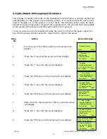
4. Input/Output Unit Logging on Procedure
The process of adding I/O Units to the SignalPoint Control Panel, is largely carried out
automatically, by the panel’s own operating system. It is usual practice for each unit to
require “logging on” to the system. In such cases, the following action must be taken.
Should the system have been received “pre-programmed”, the unit will have been added
to the system at the factory and this section will not be required.
To log on a device onto the SignalPoint, take the device in front of the panel. Insert the
key into the panel controls keyswitch, located at the right of the panel.
Step
Action
Screen Display
No
1
Turn the key to the ‘ON’ position and the screen will
display:
2
Press the ‘0’ key and the screen will now display:
3
Press the ‘
’ key until the screen displays:
4
Press the ‘YES’ key and the screen will now display:
5
Press the ‘
’ key until the screen displays:
6
Press the ‘YES’ key and the screen will now display:
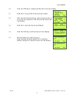
7
Enter ‘221100’ then press the ‘YES’ key and the screen
will display:
8
Press the ‘
’ key until the screen displays:
9
Press the ‘YES’ key and the screen will now display:
Panel in Access
Date
Time
|***Options **** |
>Passwords <
|Time and Date |
Yes =Select Time
| Logging |
>Fire System Opts <
| /\/\/\/\/\/\/\/\/\/\ |
Yes = select Time
| ** Fire system ** |
> Dev. Disable/Test <
| Net. Disable/Test |
Yes= Select Time
| System Mode |
>Engineers Config <
| Printer Options |
Yes= Select Time
Enter Your PIN
For Access>
Then Press YES
Time
|** Eng.; Config ** |
>Device Database <
| Sounder Options |
Yes= Select
Time
| Sounder Options |
>Log On Devices <
| Site Survey |
Yes= Select
Time
Logon DISABLED(000)
Push YES to change
Push NO to escape
Push YES/NO
Time
|**Logon Options** |
> Logon Slot :AUTO <
| Slot is :FREE |
Yes= Select
Time


