


INSTALLATION INSTRUCTIONS
serving a separate solid-fuel burning appliance.
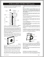
Begin the installation by locating the wall studs on the side
wall of the structure. Find the centerlines between the studs
where you want the unit to be mounted. Refer to the following
illustration (Figure 5) for a side view of how the finished
installation should look. This appliance is certified for
installation on walls which are a maximum of 12” (305 mm)
thick. The vent assembly supplied with the unit will
accomodate walls up to that thickness.
With the template flat and level against the inside wall, mark
the location for the opening for the vent assembly as well as the
location of the two holes for mounting the wall support plate
and the one for the gas supply, if the supply is to be through the
wall. If desired, (and in accordance with all applicable
building and plumbing codes) the gas piping can be brought
into the room through the floor underneath the unit.
Remove the template from the wall and with a long drill, make
a hole in the center of the opening for ventilation all the way
through inside and outside wall. Trace the wall opening in
Cutting the Vent Hole
Location of Furnace
Locating Wall Opening
Note:
The heater must be on an outside wall in the room to be heated.
When choosing a location for the furnace please remember
that the vent cap supplied with the unit must be installed
without alteration, with the exception of cutting the vent tubes
and insulation to length, as directed in these instructions. The
outside vent cap needs to be flush to the wall, so select a
relatively smooth exterior surface.
Since this appliance is a direct vent (balanced flue) design, all
combustion and ventilation air is drawn from outside of the
structure. No special considerations for combustion are
necessary inside the structure. Once you have determined that
the exterior vent will meet the clearances above, you must
locate the heater on the inside wall of the room to be heated.
Begin the installation by locating the wall studs on the inside
wall of the structure. Find the centerlines between the studs
where you want the unit to be mounted.
A full scale template is furnished with the unit which
illustrates the vent and gas supply openings and mounting
holes in their correct locations on the wall.
the figure 4 gives the required dimensions for mounting
the unit, in the event that the template is unusable or lost.
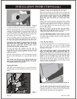
Place the template on the wall so that the vent opening will be
located between the studs and, in the case of the MV 130, for
example, the bracket mounting holes are over the studs (16” /
406 mm, on center). DO NOT CUT THE WALL STUDS IN
ORDER TO INSTALL THE UNIT. Place the bottom edge of
the template directly on the floor or the floor covering such as
carpeting or tile.
Make sure that the location you have selected for the furnace
complies the requirements above before its installation.
This gas appliance must not be connected to a chimney flue
Installing the Unit
3/16” (4.7 mm)
Mounting Holes
D
A
C
21
5/
8
” (
5
5
0
m
m
)
FLOOR
Figure 4
CLEARANCES (cont.)
J=
K=
L=
M=
clearance to nonmechanical air supply inlet to
building or the combustion air inlet to
any other appliance
clearance to a mechanical air supply inlet
clearance above paved sidewalk or paved
driveaway located on public property
clearance under veranda, porch deck, or balcony
CANADIAN INSTALLATIONS
1
US INSTALLATIONS
2
6” (15 cm) for appliances 10,000 Btu/h
(3 kW), 9” (23 cm) for appliances 10,000
Btu/h (3 kW) and
0,000 Btu/h (15 kW)
3 feet (91 cm) above if within 10 feet
(3 m) horizontally
<
>
5
<
clearance in accordance with local
installation codes and the
requirements of the gas supplier
1 In accordance with the current CSA B149.1,
.
Natural Gas and Propane Installation Code
2 In accordance with the current ANSI Z223.1/NFPA 54,
.
3 A vent shall not terminate directly above sidewalk or paved driveaway that is located between two
National Fuel Gas Code
single family dwellings and serves both dwellings.
4 Permitted only if veranda, porch, deck, or balcony is fully open on a minimum of two sides
beneath the floor.
6” (15 cm) for appliances 10,000 Btu/h
(3 kW), 12” (30 cm) for appliances 10,000
Btu/h (3 kW) and 100,000 Btu/h (30 kW)
6 feet (1.83 m)
7 feet (2.13 m)
12” (30 cm)
4
<
>
<
3
Page 8
A
10 1/4” (260 mm)
16” (406 mm)
16” (406 mm)
D
5 1/2” (140 mm)
6 3/4” (171 mm)
8 1/2” (216 mm)
E
6 1/8” (155 mm)
9” (230 mm)
9” (230 mm)
C
4 1/4” (108 mm)
4 1/4” (108 mm)
3 3/4” (98 mm)
MOD
MV 120
MV 130
MV 145
E
MV1XX-1-0603


