Empire Heating Systems MV 120 Installation Instructions And Owner'S Manual Download Page 12

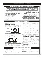
PILOT FLAME CHARACTERISTICS

MAIN BURNER FLAME CHARACTERISTICS

There will be a short blue inner flame with a much larger 
lighter blue secondary flame. The burner flame may have a 
yellow tip when hot. See the burner drawing showing the 
approximate heights of each part of the flame. Dust in the 
combustion air will produce an orange or red flame. Do not 
mistake the orange or red flame for an improper yellow flame. 
After use, cleaning may be required for the proper flame.

The correct flame will be almost horizontal, blue and will 
extend past the thermocouple 1/4" (6 mm). The flame will 
surround the thermocouple just below the tip.

On propane (LP-gas) slight yellow might occur where the pilot 
flame and burner flame meet.

Natural gas pilots require adjusting when the inlet pressure is 
above 5" w.c. (1.25kPa). Turn adjustment screw clockwise to 
reduce flame.

Propane (LP-gas) will not require adjusting.

Pilot

Flame must extend

past the thermocouple

Thermocouple

Figure 11

Figure 12

The appliance should be inspected and cleaned before using 
each year by a qualified service person. 

 the following instructions are designed to direct a 

qualified technician through the proper periodic maintenance 
and repair which may be required throughout the expected life 
of this unit. 

1. Remove the cover from the unit by removing the two nuts at 

the bottom of the unit.

Warning:

NO attempt should be made by the homeowner 

to perform these functions.

2. The gas supply should be turned OFF at the shut-off valve in 

the supply piping leading to the appliance (if installed), or at 
the gas meter or propane/ LP tank. 

3. Remove the two screws which hold the unit to the wall 

support plate and lift and pull the unit away from the wall.

4. Carefully examine the interior of the vent pipes, both large 

and small diameter. If you notice any blockage or 
obstruction, clean the pipes.

5. Look inside the openings of the rear of the unit and check for 

any foreign materials. Remove any objects which may 
block or obstruct the free flow of combustion and 
ventilation air. You will only be able to see a portion of the 
interior of the unit from this angle.

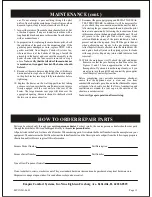
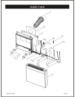
6. The main burner and pilot burner can be removed from the 

unit for cleaning by first loosening the compression fittings 

The gas to the unit 

should be disconnected so the unit can be removed from 
the wall.

that supply gas to both the main burner and pilot. Note: 
before removing either the pilot assembly or main burner 
assembly be sure to have replacement gaskets on hand. 
See Figure 13. After unscrewing the gas connection to the 
burner and removing the compression nuts, unscrew the 
thermocouple from the base of the pilot and remove it from 
the pilot assembly. Remove the four screws which hold the 
main burner/pilot plate in place, and withdraw the 
burner/pilot from the unit. Check the burner/pilot for dirt, 
lint, or a black powdery carbon deposit. If any is noted, 
brush it off completely using a soft bristled brush, or blow it 

MAINTENANCE

Burner flame

Primary flame 1/4” (6 mm) to 1/2” (13 mm)

Secondary flame 4” (102 mm) to 6” (152 mm)

Figure 13

Screws that hold

 the main burner/pilot

 plate in place

Gas connection

 to the burner

Thermocouple

Page 12

MV1XX-1-0603

Summary of Contents for MV 120

Page 1: ...ng Immediately call your gas supplier from a neighbor s phone Follow the gas supplier s instructions If you cannot reach your gas supplier callthe fire department Installation and service must be performed by a qualified installer service agencyor thegassupplier This appliance is only for use with the type of gas indicated on the rating plate This appliance is not convertible for use with other ga...

Page 2: ...duction Specifications Gas Supply Clearances Installation Instructions Lighting Instructions Pilot Flame Characteristics Main Burner Flame Characteristics Maintenance How to Order Repair Parts Parts List Parts View Troubleshooting PAGE 3 4 5 5 6 7 8 8 10 11 12 12 12 13 13 14 15 16 Page 2 MV1XX 1 0603 ...

Page 3: ... e n q u e e s t á i n s t al a d o e l a p a r a t o L a r o p au o t r o s m a t e r i a l e s i n f l a m a b l e s n o d e b e n c o l o c a r s e e n ci m a o c e r c a d e e s t e a p a r a t o C u a l q u i e rp a n t a l l a d e s e g u r i d a d o pa n e l q u e s e a r e t i r a d o p a r a r e a l i z a re l s e r v i c i o d e l e q u i p o de b e s e r r e i n s t a l a d o a n t e s ...

Page 4: ...odorlessand colorless You may not know all the following safety pre cautions which can protect both you and your family from an accident Read them carefully now then review them point by point with the members of your household Do not operate electric switches light matches use your phone Donotdoanythingthatcouldignitethegas Get everyone out of the building or area Do that IMMEDIATELY Closeall gas...

Page 5: ... Any alteration of the original design installed other than as shown in these instructions or use with a type of gas not shownontherating plate is theresponsibility of theperson andcompanymakingthechange Important Notice Always consult your local Building Department regarding regulations codes or ordinances which apply to the installation of adirectventwallfurnace 1 Installer must leave instructio...

Page 6: ...2 61kPa Propanegas models will have a manifold pressure approximately 10 0 w c 2 49kPa at the valve outlet with the inlet pressure to the valvefromaminimumof11 0 w c 2 739kPa forthepurpose of input adjustment to a maximum of 13 0 w c 3 237kPa A 1 8 3mm N P T plugged tapping accessible for test gauge connection islocatedontheoutletside ofthegascontrol LocatingGas Supply Recommended Gas Pipe Diamete...

Page 7: ...nter of theventcaptothe nearestoutsidecornerorobstruction is 16 407mm 5 The MV 120 MV 130 and MV 145 minimum wall depth is 4 1 2 114 mm and the maximum is 12 305 mm The Figure 3 Vent terminal clearances A A G C F L D E B A B C D E F G H I clearance above grade veranda porch deck or balcony clearance to window or door that may be opened clearance to permanently closed window vertical clearance to v...

Page 8: ...nttheunittobemounted A full scale template is furnished with the unit which illustrates the vent and gas supply openings and mounting holesintheir correctlocationsonthewall the figure 4 gives the required dimensions for mounting theunit intheeventthatthe templateisunusableorlost Place the template on the wall so that the vent opening will be located between the studs and in the case of the MV 130 ...

Page 9: ...comes through the wall It is not where you willcutthepipes It is very important that this be a clean straight cut for the heatertoperformproperly Remember to remove the vent assembly from the wall in ordertocut thetubes Installingtheventassemblyandwallsupportplate the indicated diameter in both walls and cut them Your hole will be about 1 to 2 26 to 52 mm depending on the unit model larger indiame...

Page 10: ...valve or at the gas meter or propane LPtankserving thebuilding Fixtheleaking jointand re testthejoints as directedabove Once the supply is checked and does not leak place the cover on the unit See Figure 10 Be sure the foam packing has been removed Secure the cover with the two nuts at the bottom of theunitwhich youhadremovedwhenunpacking eventualwaterfiltrationortheentranceofbugsisnecessary Press...

Page 11: ...he gas control knob counter clockwise to the PILOT position Depress the gas control knob and push in the Piezo igniter several times until the pilot is lit The pilot flame can be observed by looking down the inside of the heater jacket A small reflector on the right hand side near 1 Setthethermostatto lowestsetting 2 Openthe controlaccess panelonthetop rightside oftheunit 3 Turn the gas knob clock...

Page 12: ...in thesupplypipingleading to theappliance ifinstalled or at the gas meter or propane LP tank 3 Remove the two screws which hold the unit to the wall supportplateandliftandpulltheunitawayfromthewall 4 Carefully examine the interior of the vent pipes both large and small diameter If you notice any blockage or obstruction cleanthepipes 5 Look insidetheopenings of the rear oftheunitandcheckfor any for...

Page 13: ...ine with a soapy water solution Bubbles on any of the joints indicated a leak is present and must be repaired Turn OFF the gas to the unit when performing any repairs to the gas piping system After the pilot lines are checked turn the main burner ON and again check all joints in the piping system for leaks with soapy water Repair any joints which indicate a leak ispresent 12 While the main burner ...

Page 14: ...43018500 SD430185B0 SD442202B0 SK00000048 SK00000051 SD44107500 SD44105800 SD44305500 SD44177000 SD44176900 SD44175800 SD44120800 SA00000263 SD44107002 SD44107100 SD44106900 SD44106801 SK00000053 SK00000054 SD44106100 SD44158001 SD44158102 SD44125500 SD44125200 SD443332C0 SD443332D0 SD44111300 SD44132400 SD44152900 SD44153000 SK00000055 PART MV 145 N SD43018400 SD430184B0 SD44326100 SK00000049 SK0...

Page 15: ...Page 15 PARTS VIEW MV1XX 1 0603 ...

Page 16: ...ning thesmallbrassscrewonthelefthand fronttop of the gas control top plate Backing the screw out counterclockwise increases the pilot flame The pilot flame should contact the thermocouple tip but not excessively long SeeLightingInstructions the thermocouple is a standard 24 millivolt probe Check its effectiveness by removing it from the heater and attach a probe alligator clip to themagnetcontactb...

Reviews: