background image

E-mail: [email protected]

Made in Rome, New York, USA

6

SUPERHEA

T CHARGING CHAR

T

FIELD CHARGING

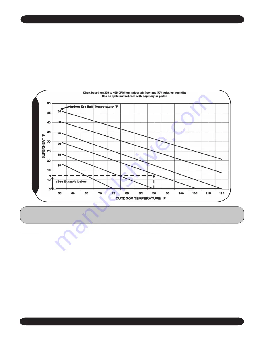
Example:

1. Suction pressure is 65 psi. which equals 38

°

 F on 

The 

R-22  Scale of the Low-Side Gauge.

2. Suction line temperature taken at the unit is 70

°

 F. 70

°


F minus 38

°

 F equals 32

°

 F superheat.

3.  Outdoor  temperature  is  90

° 

F;  indoor  temperature  is 

80

°

 F.

4.  Intersection  of  the  indoor-temperature  and  outdoor-

temperature lines occur on the 12

°

 F superheat line. 

5. Add charge to obtain 12

°

 F superheat.

Instructions:

1. Measure suction pressure and determine evaporator-

refrigerant  temperature  on  R-22  scale  of  low-side 

gauge.

2.  Measure  suction-line  temperature  on  suction  line  of 

the unit.

3. Measure outdoor and indoor temperatures.

4.  Determine  from  the  table  what  the  superheat  should 

be for the indoor and outdoor temperatures. (Example 

indicates 12

°

 F superheat.) 

5. Adjust  charge  if  needed.  Be  sure  unit  is  running  at 

stabilized condition.

The use of the superheat method is highly recommended 

for  field  charging  or  checking  the  existing  refrigerant 

charge in a system. Because each installation is different 

in terms of indoor air flow, refrigerant line length, etc.., the 

factory charge may not be correct for every application. 

To assure the best performance from the air-conditioner, 

the refrigerant charge should be checked and adjusted, if 

need be, on each installation. 

For  proper  superheat  readings,  a  standard  low-side 

refrigerant  gauge  and  an  accurate  thermometer  is 

needed. A  mercury  or  stem-type  thermometer  is  not 

adequate for suction-line temperatures. We recommend 

electric  thermocouple  thermometers  (available  at  most 

refrigeration wholesalers); however an accurate remote-

bulb thermometer can be used. When measuring the line 

temperature, be sure the thermometer is well installed to 

assure  accurate  measurements. The  chart  below  gives 

superheat values at various outdoor temperatures. Allow at 

least 5 minutes running time between charge adjustments 

for the unit to stabilize.

Note: 

If operating superheat is more than 5

°

 F above the chart value, add refrigerant. If below the chart 

value remove refrigerant. If below the limit line, remove refrigerant.

Summary of Contents for MC2 Series s

Page 1: ...com INSTALLATION OPERATION AND MAINTENANCE MANUAL EMI AMERICASERIES SINGLE ZONE MULTI ZONE CONDENSING UNITS MC4 MH4 MULTI ZONE MC2 MH2 DUAL ZONE SCC SHC SINGLE ZONE STRAIGHT COOL HEAT PUMPS Nominal Ca...

Page 2: ...er_________________________ Date of installation______________________ SAFETY INSTRUCTIONS Read all instructions before using the EMIAmericaSeries high ef ciency condensing unit Install or locate this...

Page 3: ...may cause damage to the compressor and coil and could result in freezing that may void the warranty We accomplish the low ambient operation on our condensers by cycling the condenser fan When in low...

Page 4: ...alent feet Whether the outdoor unit is above or below the indoor unit a P trap is recommended if the suction riser is 20 feet or higher NOTE Avoid excessive oil buildup The P trap should have a shallo...

Page 5: ...panels and make sure they are properly secured Make nal visual inspection and repair any de ciencies NOTE A hard start kit may be required for units in low volt age frequent cycle applications OPERATI...

Page 6: ...ommended for field charging or checking the existing refrigerant charge in a system Because each installation is different in terms of indoor air ow refrigerant line length etc the factory charge may...

Page 7: ...80 198 5 215 5 235 0 203 5 212 0 226 0 237 0 85 208 5 230 5 252 0 218 0 227 0 242 5 253 0 90 223 0 246 0 270 0 233 5 241 5 259 0 270 0 95 241 5 263 0 285 0 250 5 256 0 275 5 285 0 100 264 0 280 5 300...

Page 8: ...1 0 125 5 4 32 6 4 240 7 8 15 18EF 1 0 125 6 5 44 7 5 240 9 1 15 24EF 1 0 125 8 2 58 9 2 240 11 3 15 30EF 1 0 125 10 4 72 11 4 240 14 0 20 36EF 1 8 0 333 13 90 14 8 240 18 1 30 220 240 50 Hz 09FA 220...

Page 9: ...52 OZ 46 5 OZ 49 5 OZ 56 5 OZ 55 OZ 58 OZ 65 OZ 18 CHP 24 FHP 24 WHP 18 TBH 24 CAH 24 56 OZ 10 25 50 6 OZ 14 OZ 28 OZ 35 OZ 41 OZ 41 OZ 49 OZ 63 OZ 47 OZ 55 OZ 69 OZ 24 CHP 24 FHP 24 WHP 30 TBH 24 CA...

Page 10: ...rankcase heater This will offer protection against cold start situations thus prolonging the life of the compressor NOTE The crankcase heater is installed when the low ambient control option is select...

Page 11: ...8 20 6 7 48 9 6 60 21 9 24 3 30 197 9508 1 8 0 33 3 8 20 6 7 48 7 4 48 19 7 21 6 25 197 2208 1 0 125 4 8 26 3 4 8 26 3 7 4 48 18 19 9 25 197 2008 1 0 125 4 8 26 3 7 4 48 13 2 15 1 20 197 9999 1 0 125...

Page 12: ...erant charge protection NOTE The crankcase heater is installed with 9 15K Btu heat pumps and when the low ambient control option is selected MC2 MH2 DUAL ZONE High Ef ciency Condensing Unit Limited Ra...

Page 13: ...0 0 125 4 8 26 3 4 8 26 3 10 6 11 8 15 9200 208 230 60 1 1 0 0 125 3 8 20 4 8 26 3 9 6 10 8 15 5500 208 230 60 1 1 8 0 25 6 4 38 6 4 38 14 6 16 2 20 1 Circuit Designators 9 9 000 Btuh 2 12 000 Btuh 5...

Page 14: ...unit SCC SHC pg 8 MC4 MH4 pg 9 MC2 MH2 pg 11 or call the factory Anti short cycle protection should be used on systems that use a con ventional thermostat Evaporator Entering Air WB Evaporator Leaving...

Page 15: ...others Failure to start due to voltage conditions blown fuses open circuit breakers or other damages due to the inadequacy or interruption of electrical service Damage or repairs needed as a consequen...

Page 16: ...E mail emi enviromaster com Made in Rome New York USA 16...

Reviews: