background image


EM-GS User's Manual


5. Control Panel and Operation


15 

5.3 Parameters code function explanation 

The parameter “

Fb

” is used to set the control ways of soft starter; as the following form: 

Numerical value   

Keypad 

External terminal control 

RS485 Communication 

Note:

 In the above form,"1" is allowing,"0" is forbidding. For example, If you press keypad "RUN", and meet 

"Error 14"

, please set "

Fb

=0". And then soft starter can be run by keypad. 

If the "External Control" is allowing, you must contact a normally closed switch button between the terminal 

⑦⑧


and terminal 

, otherwise the soft starter can’t start-up the motor and show "

Error1

/

Error 16

". 

The parameter

 "FE" 

is use to setting the way of 

&

 programmable relay output, As the following form: 

Numerical Value of FE


The moment of programmable relay output 

0(10)


When sending the order of starting , the program output 

1(11)


When beginning to start , the program output 

2(12)


When at the start of bypass operation, the program output 

3(13)


When sending the order of stopping, the program output 

4(14)


When finishing the operation of stopping, the program output 

If users need programmable relay output time delay, the time can be setting by parameter

 "F4"

.   


When the

 "FE"

 is setting as 5~9(or 15~19), the terminal 

&

 will display the state of programmable relay 

output, As the following form:   

The number setting by FE

  The state of programmable relay output 

5(15)


Error state 

6(16)


Working state 

7(17)


Ready state 

8(18)


Starting state 

9(19)


By-pass operation state 


The state of programmable relay output is used to show the working state of soft starter, and under this way, the


"F4"

 setting delay time is invalid;   


The default setting of

 "FE"

 code is "7" showing the ready state of soft starter and at this state the motor can be 

started up; 


When the 

"FE"

 code is "5" outputting error state of motor, Terminal 

③  ④

 can output fault such as: (Err05, 

Err06, Err07, Err08, Err12, and Err15). This will not affect the function of 

⑤⑥

 error output terminals. 


When 

"FE"

 >9, the programmable output will be “reverse phase output”, (Normal open will reverse to normal 

close). 


When 

"FC"

=0, all parameters cannot be revised. And when

 "FC"

=1, (F4; F6; Fd; FE; FF; FU) cannot be 

revised. When 

"FC"

=2, all parameters can be revised. 


"FU"

  is motor less load protection, when 

"FU"

10,the motor less load protection is invalid. The 

"FU"


less load protection current range is 10%~90%. And delay time is 5~90 seconds. The ten bits*10% is 

protection current percentage, the Bits*10 is delay time; the bits=0, the delay time is 5seconds. 

For example: 

"FU"

=42, the less load current is 40%, and delay time is 20 seconds.   

5.4 Helping message and explanation 

When the product is not starting or stopping ,or not at the ”set” state, you can press “YES” key and come into 

helping  menu ,then press the "Up"  or "Down"  key to choose the help message. Please press "YES" or 

"STOP&RSET" key to return.   

Summary of Contents for EM-GS Series

Page 1: ... an District Shenzhen China Phone 86 0755 29985851 Fax 86 0755 29970305 Zip code 518101 Website www emheater com China EM Technology Limited User s Manual EMHEATER EM GS Series Soft Starter Asia Europe Africa South America North America Southeast Asia Oceania EMHEATER ...

Page 2: ... Clauses Please check this user manual carefully before using the product Only the technical person is allowed to install the product To be sure that the motor is correctly matched with the soft starter It is forbid to connect capacitors to the output terminals U V W Please seal the terminal switch insulation glue after finishing connect them The soft starter and its enclosures must be fixedly ear...

Page 3: ... 2 Parameters set and explanation 13 5 3 Parameters code function explanation 15 5 4 Helping message and explanation 15 5 5 The complete solution of default setting and user debugging 16 6 Protection Functions and Directions 17 6 1 Protection classes and explanation 17 7 Test Run and Application 19 7 1 Power on to test running 19 7 2 The starting mode and application 20 7 2 1 Current limit to star...

Page 4: ...ng the service life of the motor and related equipments Soft stopping function can effectively solve the parking surge problem of inertial systems That is a traditional starting equipment cannot be achieved With six unique starting mode To adapt to the complex motor and load achieve perfect priming effect With complete and reliable protection function effectively protect the safety of motor and re...

Page 5: ... External control COM control 5 Operation panel external COM control 6 Operation panel COM control 7 COM control 8 No start or stop operation Start Mode 1 Current limiting to start 2 Voltage ramp to start 3 Torque control current limiting to start 4 Torque control voltage ramp to start 5 Current ramp to start 6 Voltage current limiting double closed loop start Stop Mode 1 Soft stop 2 Free stop Pro...

Page 6: ...tion with good ventilation free from corrosive gas and conductive dust Altitude Below 1000M It have to rise the rate power when the altitude is more than 1000M Temperature 30 55 o C Humidity 90 RH without dew condensation Vibration 0 5G Structure Protection Class IP20 Cooling Pattern Natural wind cooling ...

Page 7: ... hesitate to contact us with any request for additional information Check up the type of product whether it is the right one you order Nameplate explanation Diagram 2 1 Model explanation Diagram 2 2 Check any damage to the product because of the transport such as the spare parts are apart from the main body or the shell be damage etc Check others including the user s manual ...

Page 8: ...o the loading equipments Cooling Mode Naturally wind cooling Protective Grade IP20 Environment Conditions when altitude is less than 1000m the temperature of the environment should be between 25o C 40 o C relative humidity should be less than 90 RH no vapor no flammable volatile corrosive gas No electric dirt indoor installation ventilated vibration is less 0 5G 3 2 The installation requirement Th...

Page 9: ... 131 247 M6 5 EM GS2 7d5 EM GS3 015 EM GS4 015 15 30 146 270 160 131 247 M6 5 EM GS3 018 EM GS4 018 18 5 37 146 270 160 131 247 M6 5 EM GS2 011 EM GS3 022 EM GS4 022 22 43 146 270 160 131 247 M6 5 EM GS2 015 EM GS3 030 EM GS4 030 30 60 146 270 160 131 247 M6 5 EM GS2 018 EM GS3 037 EM GS4 037 37 75 146 270 160 131 247 M6 5 EM GS2 022 EM GS3 045 EM GS4 045 45 90 146 270 160 131 247 M6 5 EM GS2 030 ...

Page 10: ...560 245 260 465 M8 25 EM GS2 160 EM GS3 280 EM GS4 280 280 560 290 560 245 260 465 M8 25 EM GS2 185 EM GS3 320 EM GS4 320 320 640 290 560 245 260 465 M8 25 EM GS2 200 EM GS3 400 EM GS4 400 400 800 330 590 245 300 490 M8 32 EM GS2 220 EM GS3 450 EM GS4 450 450 900 330 590 245 300 490 M8 32 EM GS2 250 EM GS3 500 EM GS4 500 500 1000 450 740 300 400 575 M10 40 EM GS2 315 EM GS3 600 EM GS4 600 600 1200...

Page 11: ...3 Usage Condition and Installation EM GS User s Manual 8 Diagram 3 6 ...

Page 12: ...e connected with terminal when the starter works normally But if these two terminals are open the soft starter will stop and at this time the starter is at the state of fault protection This terminal can be controlled by the normally closed output terminals of external protection device and it is useless when the FA code is set to 0 Primary protection Terminal are startup or stop input There are t...

Page 13: ...5 is RS232 output is RS232 input is 5V output limit current is 50mA is earthed GND are empty The user can choose the following software Computer collector distribution control communication software Device Net interface card and communication Device Net Mod bus Profi bus gateways Others ...

Page 14: ...EM GS User s Manual 4 Connection and External Terminal 11 Diagram 4 5 ...

Page 15: ...lon is revisable and press UP key or DOWN key to change parameter And then press YES key to save the screen will show GOOD and ring two means parameter saved and then quit If you do not want to save new parameter to press SET key the colon stop flashing and recover old paramater and to press YES key to quit also can directly go back to main menu by pressing STOP RSET key YES key Under non setting ...

Page 16: ... will free stop One soft starter for 2 motor this code should set 0 F3 Start up time delay 0 999S 0S Delay is with countdown mode If set as 0 the starter will start up the motor immediately F4 Programming time delay 0 999S 0S This code is used to set delay time of terminals output Set 0 immediately close F5 Start up current limited value 50 500 400 It is used when the staring mode is current limit...

Page 17: ...5 3 FF Soft stopping limited current 20 100 80 Setting the detailed in Item 7 3 FP Motor rated current Rated value The rated current of motor is the same as the motor nominal current FU Motor less load protection 0 99 Prohibit Setting the detailed in Item 5 3 FL 3 phase balance valid 0 1 1 0 Invalid 1 Valid FM Current coefficient 50 150 100 Showing current slants high to set coefficient down Lower...

Page 18: ...elay output As the following form The number setting by FE The state of programmable relay output 5 15 Error state 6 16 Working state 7 17 Ready state 8 18 Starting state 9 19 By pass operation state The state of programmable relay output is used to show the working state of soft starter and under this way the F4 setting delay time is invalid The default setting of FE code is 7 showing the ready s...

Page 19: ...pping and not in setting state to press YES key to enter helping menu and press UP or DOWN key to choose helping information Under state of helping to press YES key or stop key to quit helping menu 5 5 The complete solution of default setting and user debugging The system integrator or final user do not have proper motor for testing but you can use star wiring by 3 piece 100W or 200W electric lamp...

Page 20: ...ayed time 0 5s When power voltage is less than 80 the protection delayed time 3S Over voltage protection delay time When power voltage is more than 140 the protection delayed time 0 5S When power voltage is more than 120 the protection delayed time 3S Loads short circuit protection delay time The protection delayed time 0 1S Motor less load protection delay time The protection range 10 90 is set b...

Page 21: ...nd 15 Second 30 Second 15 Second The 5 times of F6 current Overload drop away time The multiple to the rated current 3 4 5 3 4 5 3 4 5 3 4 5 They are the typical values Drop away time S 4 5 2 2 1 5 23 12 7 5 46 23 15 23 12 7 5 Diagram 6 1 IEC60947 4 2 standard Motor heat protection curve overload drop away time Remark FP set value should be same as motor nameplate rated current The FP set value sh...

Page 22: ...ower on or be in starting the error lamp is lighting and screen displays Err at this time you can check diagram 7 1 to find out reason Press STOP key or external stop button can reset the error state Note When ambient temperature is less than 10 the starter should be power on to preheat for 30 minute and then to start Error Code Explanation Reason and the solution way Error 0 The fault is removed ...

Page 23: ...essfully and will close to suck by pass contactor running At this time if the contactor is not closed the motor will stop running so you can check whether the wiring of the bypass contactor is right 7 2 The starting mode and application The EM GS series soft starter has six starting modes for the user to select according the motor and load equipments 7 2 1 Current limit to start The F9 code is set...

Page 24: ...ut strictly current limitation case Note T is the automatic detecting starting time according to load It will be less than set time when the load equipments are light this starting mode fits for the common occasions where the motor need to be started smoothly Diagram 7 2 7 2 3 Torque control current limit or voltage ramp to start The F9 code is set as 2 or 3 Diagram 7 3 and 7 4 shows the output ch...

Page 25: ...mit value through the FF code to reduce the high current shock to the motor when stopping This current limit value is percentage of F5 7 3 2 Free stopping Mode The F2 code is set as 0 When using this mode to stop the motor the soft starter will cut off the connection to the bypass contactor and forbid the controlled silicon output voltage after receiving stopping command The motor stops gradually ...

Page 26: ...le by lightning or other reasons such as over voltage over current surge interference Please refer to SPD related documents for details 7 5 Application examples The parameters of the different loads are different please refer to diagram 7 2 The loading Voltage ramp starting time s Voltage ramp stopping time s Initial voltage Voltage ramp current limit Current limit to start Ball mill machine 20 6 ...

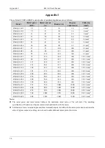
Page 27: ...3 132 132 264 315 400 30 4 mm2 EM GS3 160 160 320 350 400 30 4 mm2 EM GS3 185 185 370 400 400 30 4 mm2 EM GS3 200 200 400 400 400 50 5 mm2 EM GS3 250 250 500 630 630 50 5 mm2 EM GS3 280 280 560 630 630 50 5 mm2 EM GS3 320 320 640 630 630 50 5 mm2 EM GS3 355 355 710 1000 1000 60 6 mm2 EM GS3 400 400 800 1000 1000 60 6 mm2 EM GS3 450 450 900 1000 1000 60 6 mm2 EM GS3 500 500 1000 1250 1000 80 6 mm2 ...

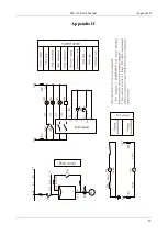
Page 28: ...EM GS User s Manual Appendix II 25 Appendix II ...

Page 29: ...Appendix II EM GS User s Manual 26 ...

Page 30: ...caused by improper transit or storage after purchase Induced failure or aging of the device due to poor ambient Malfunction or damage caused by fire flood thunder earthquake abnormal voltage or other natural disasters Unidentifiable nameplate mark and ORD number due to intentional spoilage Delayed or unsatisfied payment in violation of purchase appointment Fail to give an objective description on ...

Reviews: