background image

7

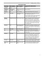
DIAGNOSTIC TABLE

DS 1 (Red)

DS 2 (Green)

Error/Condition

Comments/Troubleshooting

Simultaneous 
slow flash

Simultaneous slow 
flash

Normal operation

No fault

Simultaneous 
fast flash

Simultaneous 
fast flash

Normal operation with call 
for heat

Normal operation

Slow flash

On

Open limit switch

Verify continuity through rollout switch circuit

Off

Slow flash

Pressure switch stuck 
closed/open

Pressure switch stuck closed. Check switch func-
tion, verify inducer is turning off.
Pressure switch stuck open. Check pressure switch 
function and tubing. Verify inducer is turning on and 
pulling sufficient vacuum to engage switch.

Alternate 
slow flash

Alternate slow flash External lockout (retries)

Failure to sense flame is often caused by carbon 
deposits on the flame sensor, a disconnected or 
shorted flame sensor lead or a poorly grounded 
furnace. Carbon deposits can be cleaned with em-
ery cloth. Verify sensor is not contacting the burner 
and is located in a good position to sense flame. 
Check sensor lead for shorting and verify furnace 
is grounded properly.

Slow flash

Off

Flame sensed with gas 
valve de-energized

Verify the gas is operating and shutting down prop-
erly. Flame in burner assembly should extinguish 
promptly at the end of the cycle. Check orifices and 
gas pressure. 

On

Slow flash

Open rollout switch

Verify continuity through rollout switch circuit. 

On 

On

Module – internal fault 
condition

Module contacts for gas valve not operating or 
processor fault. Reset control, if condition persists, 
replace module. 

Slow flash

Fast flash

Low flame sense current

Low flame sense current is often caused by carbon 
deposits on the flame sensor, a poorly grounded 
furnace or a mis-aligned flame sense probe. 
Carbon deposits can be cleaned with emery cloth. 
Check or improve furnace and module ground. 
Verify sensor is located in or very near flame as 
specified by the appliance manufacturer.

Fast flash

Slow flash

Grounding or reversed 
polarity

Verify the control and furnace are properly ground-
ed. Check and reverse polarity (primary) if incorrect.

Alternate fast 
flash

Alternate fast flash

Module ignitor contact 
failure

 Fault code indicates the module ignitor contacts 
are not functioning properly. Replace module.


 TROUBLESHOOTING

Summary of Contents for White-Rodgers 21D83M-843

Page 1: ...act with water dripping spraying rain etc If the control has been in direct contact with water replace the control Label all wires before disconnection when servicing controls Wiring errors can cause improper and dangerous operation Route and secure wiring away from flame SHOCK HAZARD Disconnect electric power before servicing Ensure proper earth grounding of appliance Ensure proper connection of ...

Page 2: ...idual products of combustion between the failed trial for ignition and the retry period 15 Post Purge The period of time intended to allow for the dissipation of any unburned gas or residual products of combustion at the end of a furnace burner operating cycle Post purge begins at the loss of flame sense 5 Lockout Time ANSI standard rated module timing 250 Heat Delay To Fan On The period of time b...

Page 3: ...cement 50A66 843 ignition control board over the holes marked A in figure 1 Insert the replacement control stand off fasteners into the holes in the mounting panel 6 Insert the four provided stand off fasteners into the back of the mounting panel in the holes marked B in figure 1 Insert the replacement control board assembly into the existing holes in the control box or blower panel 7 Insert provi...

Page 4: ...ue transformer wire Optional 4 blue wire provided for transformers that have a quick connect terminal 6 Connect the provided 9 pin to 12 pin wiring harness to the unit 9 pin connector 7 Connect the provided 4 pin to 6 pin wiring harness to the unit 6 pin connector 8 Connect the yellow wire from position 6 on the 12 pin connector to the yellow transformer wire 9 Connect GND wire to equipment ground...

Page 5: ...te with the 50A66 843 s adap tive ignition routine to ensure the most efficient ignitor temperature At the end of the ignitor warm up time both valves in the gas valve are opened Flame must be detected within 4 seconds If flame is detected the delay to fan on period begins After the delay to fan on period ends the circulator fan is energized at heat speed If there is an optional electronic air cle...

Page 6: ...out or a shorted or open condition in the flame probe circuit will be sensed within 2 seconds The gas valve will de energize andthecontrolwillrestarttheignitionsequence Recycles will begin and the burner will operate normally if the gas supply returns or the fault condition is corrected before the last ignition attempt Otherwise the control will go into system lockout If the control has gone into ...

Page 7: ...ng and verify furnace is grounded properly Slow flash Off Flame sensed with gas valve de energized Verify the gas is operating and shutting down prop erly Flame in burner assembly should extinguish promptly at the end of the cycle Check orifices and gas pressure On Slow flash Open rollout switch Verify continuity through rollout switch circuit On On Module internal fault condition Module contacts ...

Page 8: ...White Rodgers is a business of Emerson Electric Co The Emerson logo is a trademark and service mark of Emerson Electric Co white rodgers com emersonclimate com ...

Reviews: