background image

Reference Manual 

Start Up Procedure 

00809-200-4245 

April 2022 


Reference Manual 

27


Start Up Procedure 

 WARNING


HIGH PRESSURE AIR 

Serious injury or death could occur. 
The compressed air supply operate at pressures that can cause injury. 


 CAUTION


AIR SUPPLY 

Minor or moderate injury will or could occur 
Air provided must be connected from a pressure regulated clean, filtered and moisture free 

supply source. 


NOTICE


HEAVY ITEM 

To stop the start-up procedure at any time, set the main circuit breaker to OFF. 


4.1  Before You Begin 

Remove all outside encumbrances from the area around the conveyor Secure the 

conveyor to its location 

4.1.1 

Prior To Startup 
All guard doors must be closed and latched.  There are two guard doors, one on either 

side of the conveyor.  The conveyor will not start if the doors are not latched properly. 


Summary of Contents for ROSEMOUNT HMC-C01

Page 1: ...Reference Manual 00809 200 4245 Rev AA April 2022 HMC C01CompressionSampleHead ...

Page 2: ...oth to this publication and the products which it describes No part of this publication may be reproduced stored in a retrieval system or transmitted in any form or by any means electronic mechanical photocopying recording or otherwise without the express prior written permission of the copyright holder If you require additional technical assistance request help from cascade support emerson com or...

Page 3: ...ervicing the product If you do not understand the instructions contact cascade support emerson com for additional clarification Follow all warnings cautions and instructions marked on and supplied with the product Inform and educate your personnel in the proper installation operation and maintenance of the product Install your equipment as specified in the installation instructions of the appropri...

Page 4: ...maintaining the leak detection system must be instructed trained and qualified with the operating company and the manufacturer It is the operating company s responsibility to Train staff Observe safety regulations Follow the safety instructions and procedures in the product manual Operators must Be trained Read and understand all relevant sections of the product manual before commencing work Know ...

Page 5: ...viceable must be collected separately and disposed of in an environmentally correct manner Regulation standards Description IEC 61010 1 2010 AMD1 2016 CSV UL Std No 61010 1 3rd edition Safety requirements for electrical equipment for measurement control and laboratory use Part 1 General requirements IEC 61326 1 2020 Electrical equipment for measurement control and laboratory use EMC requirements P...

Page 6: ...ional or unintentional unauthorized use Physical security is an important part of any security program and fundamental to protecting your system Restrict physical access to protect users assets This is true for all systems used within the facility Safety precautions The precautions in this manual MUST NOT be changed amended or removed All authorized users installation operation and maintenance per...

Page 7: ...r is fixed during the manufacture and defined on the ratings label fitted to the unit The voltage at the installation site must meet the rated voltage required WARNING MAINTENANCE Serious injury or death could occur Only authorized maintenance personnel can carry out repair work on the leak detection system On completion verify All tools and equipment are removed No contamination water dust is in ...

Page 8: ...e the leak detection system unless it is physically secured in position and all electrical and sample gas connections are in place CAUTION AIR SUPPLY Minor or moderate injury will or could occur Air provided must be connected from a pressure regulated clean filtered and moisture free supply source ...

Page 9: ...9 Safety and system labels and annotation Labels are applied to the system in the positions shown below Location Label Type Label Fitted ...

Page 10: ...10 Rosemount HMC C01 ...

Page 11: ...ntify chain and sprockets 22 3 3 2 Sprockets and wear strip position 22 3 3 3 Align drive and idler sprockets 22 3 3 4 Idler Wheel and Sprocket Locations 22 3 3 5 Inspect guide clearance in both straight and corner sections 22 3 3 6 Insert section of chain 23 3 4 Inspect Conveyor 23 3 4 1 Installation Chain 23 3 4 2 Installation the Catenary Sag 24 3 4 3 Installation Disassembly Chain 24 3 4 4 Con...

Page 12: ...MAINTENANCE 34 6 1 1 Flat Top and Friction Top Maintenance 34 6 1 2 Inspection 34 6 1 3 Chain and Sprockets 35 6 1 4 Flat Top Friction Top Chain 35 6 1 5 Bearing Lubrication 36 6 1 6 Acceptable lubricants include 36 6 1 7 Motor Maintenance 36 6 1 8 Reducer Maintenance 37 6 1 9 Manufacturers Recommended Lubricants 37 Chapter 7 Troubleshooting 39 ...

Page 13: ...e depending on the specific application The compression head is designed to be installed alongside the CM 01 base leak detection system Please refer to reference manual 00809 0100 4245 for details on the base unit installation This document is intended for the personnel who install operate and maintain the detector The compression head is designed to be installed as a slot in solution on an existi...

Page 14: ...System Overview Reference Manual 00809 200 4245 April 2022 14 Rosemount HMC C01 D Reject Station E Electrical Panel F Control Station G Compressed Air Preparation ...

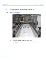
Page 15: ... 200 4245 April 2022 Reference Manual 15 2 Equipment and Accessories 2 1 Base Conveyor A Flat top conveyor surface B Guide rails adjustable for different package sizes C Package purge point compressed air knife directed at the surface of the packages ...

Page 16: ...de of the system The net effect is a slight positive pressure is created inside the enclosure which prevents ingress of contaminated air If uncontaminated air needs to be ducted in from another source then this can be done with the 100mm duct fitting on top of the purge fan 2 4 Reject Station The reject station is located after the compression conveyor and has 3 modes of operation 1 Normal in this...

Page 17: ...ion can be disabled by not providing reject signal from the CT4215 base system 2 6 Electrical Panel The system electrical panel is shown below The panel contains the following key components Safety control circuit network hub isolation switch PLC 3 phase to single phase transformer Power supplies and conveyor drives ...

Page 18: ...Controls From left to right A Start B Stop C Reset D Emergency Stop These controls will be covered in more detail in the statup shutdown section 2 8 Compressed Air Preparation The components inside the compressed air preparation box are A Regulator B Solenoid This solenoid connects to the reject signal ...

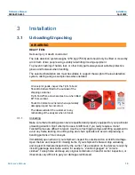
Page 19: ...ally damaging impact has occurred The labels will alert the customer to any mishandling of the analyzer when in transit 3 1 1 Unloading Make sure that unloading personnel are qualified and properly equipped for your particular unloading situation Don t attempt to use a forklift truck if you really require a crane Twisted frames are difficult to repair Use the correct rigging slings and lifting equ...

Page 20: ...drive components are mounted to the drive section Cross reference your packing slip and or approval drawings In the event you find a part that you feel you do not need or is not correct for your conveyor please contact our Customer Service Department 3 2 Installation WARNING HEAVY ITEM Serious injury or death could occur The leak detection system weighs 1250 kg 2756 lb and should only be lifted or...

Page 21: ...accidents when material jams It safeguards personnel from electrical shock injuries It safeguards the machine and its connecting wires from major short circuit current damage It also safeguards the machine from slight amounts of over current that can slowly overheat motors wire and cause fires WARNING ELECTRICAL CODE REQUIREMENTS Serious injury or death could occur Many conveyors can be electrical...

Page 22: ...3 Align drive and idler sprockets Make sure that the drive and idler sprockets are aligned axially with the center of the chain Lock the sprockets in place using the keyway and setscrews If multiple strands share a tail shaft key only one sprocket and allow others to rotate Collars should be utilized to prevent axial floating 3 3 4 Idler Wheel and Sprocket Locations The idler wheels can only be us...

Page 23: ...maged or embedded with debris replace them as necessary CAUTION Minor or moderate injury will or could occur All machinery must be turned off and locked out prior to chain installation inspection maintenance or removal Care should be used when handling the chain to avoid crushed or pinched fingers Keep the chain under control at all time The chain can easily be twisted causing permanent deformatio...

Page 24: ...t section separate the chain to required length using a drift punch and hammer to drive appropriate connecting pin out of chain Make final connection to complete the chain loop 3 4 4 Connect the chain One Piece Chains with Style D Pins To connect each 10 ft section start by positioning the connection pin into either one of the double eyes in the appropriate end link Take care in positioning the fl...

Page 25: ...s to secure the connecting link 3 4 7 Connection style may vary by chain series To install the last section of chain separate the chain to require length using a chain breaker to push the appropriate connecting pins out of the roller base chain Make final connection to complete the chain loop For plastic two piece chains white top plates are provided to aid in the location of the connecting links ...

Page 26: ...Installation Reference Manual April 2022 00809 200 4245 26 Rosemount HMC C01 ...

Page 27: ...ided must be connected from a pressure regulated clean filtered and moisture free supply source NOTICE HEAVY ITEM To stop the start up procedure at any time set the main circuit breaker to OFF 4 1 Before You Begin Remove all outside encumbrances from the area around the conveyor Secure the conveyor to its location 4 1 1 Prior To Startup All guard doors must be closed and latched There are two guar...

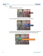
Page 28: ... Startup Pull the E STOP button solid red UP Press the BLUE flashing light until solid blue the green light will flash Press and Hold the Green Button until no longer flashing approximately 3 5 seconds An alarm will sound the status indicator light will go green and the conveyor will start ...

Page 29: ...down the conveyor 4 1 4 Shutdown Remove all product from conveyor Push the RED stop button Safety Information If product sticks in the compression area of the conveyor press the EMERGENCY STOP button NEVER stick your hand or any part of your body or any other object into any area of the conveyor while it is in operation Wait for the conveyor belt chain to stop moving before removing stuck product ...

Page 30: ...Start Up Procedure Reference Manual April 2022 00809 200 4245 30 Rosemount HMC C01 ...

Page 31: ...In general provided the following section is followed the leak detector is a reliable system requiring limited maintenance or intervention by the customer Note There is no need for a customers to access components not covered in this document For further assistance contact cascade support emerson com ...

Page 32: ...Scheduled Maintenance Reference Manual April 2022 00809 200 4245 32 Rosemount HMC C01 ...

Page 33: ...amages At Delivery Inspect Shipment for missing parts At Delivery Locate read and protect your instruction manual At Delivery Check conveyor levelness and true ness At Installation Clean around operator areas infeed and discharge Daily Check inside the frame for material build up Weekly Clean off motor and reducer Monthly Check and adjust belting take up tension Monthly Check frame for corrosion c...

Page 34: ...s for maximum performance Keep a record to show the equipment serviced the date of inspections the results the parts required or replaced and the cause of the trouble If possible keep a log sheet on each conveyor so the proper servicing may be easily maintained Qualified and trained personnel shall perform maintenance such as lubrication and adjustment Where a lack of maintenance would cause a haz...

Page 35: ...rns A lubrication system that provides continuous and uniform lubrication is recommended If lubrication is not acceptable or compatible with the application a short break in lubrication application is beneficial The service life of side flexing chains and wear strips can be improved if sliding surfaces are lubricated with a light material oil prior to installation In the case of side flexing rolle...

Page 36: ...ss lube from the shaft seals so you can observe the amount of newly expelled grease Remember to tighten the bearing set screws BI annually while doing the greasing 6 1 6 Acceptable lubricants include Socony Mobil Oil Company Armvac No 781 Keystone Lubricant Company 84 H Light Standard Oil Company of Indiana Stanolith No 57 Sinclair Oil Company Litholene Texas Oil Company Multi Fak No 2 Mobil SHC P...

Page 37: ...Recommended Lubricants Manufacturer AGMA Compound 7 AGMA Compound 8 15 60 oF Ambient Temp 50 125oF Ambient Temp Amoco Oil Company Worm Gear Oil Cylinder Oil 680 Chevron USA Inc Cylinder Oil 460 Cylinder Oil 680X Exxon Co USA Cylesstic TK 460 Cylesstic TK 680 Gulf Oil Co Senate 460 Senate 680D Mobil Oil Corp 600W Super Extra Helca Super Shell Oil Co Valvata Oil J460 Valvata Oil J680 Sun Oil Co Gear...

Page 38: ...Scheduled Maintenance Reference Manual April 2022 00809 200 4245 38 Rosemount HMC C01 ...

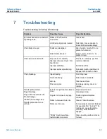
Page 39: ...shaft drop Set shaft per Rex Improper sprocket positioning Sprockets must be positioned to engage tooth pocket on chain Chain breakage Impact loading Don t drop load Over back flexing Return roller to small dia Jam up Clear cause of jam Pins coming out End plugs missing check or replace Transfer plate problem Finger breakage Finger climb top of chain ribs Product tippage Cracks thru mounting holes...

Page 40: ... Problem Possible Cause Possible Solution Rapid or unusual chain wear Wear tracks Don t use plastic wear tracks on glass lines where breakage occurs Don t use a dead soft stainless steel Rapid sprocket tooth wear Abrasive debris Most commonly a problem when using plastic sprockets ...

Page 41: ...Reference Manual Troubleshooting 00809 200 4245 April 2022 Reference Manual 41 ...

Page 42: ...n All rights reserved Emerson Terms and Conditions of Sale are available upon request The Emerson logo is a trademark and service mark of Emerson Electric Co Rosemount is a mark of one of the Emerson family of companies All other marks are the property of their respective owners ...

Reviews: