


3
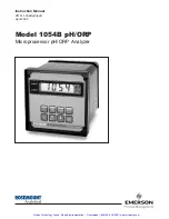
MODEL 1054B pH/ORP
SECTION 2.0
INSTALLATION
SECTION 2.0
INSTALLATION
2.1 GENERAL.
This analyzer's enclosure is suitable
for outdoor use. However it should be located in an
area where temperature extremes and vibrations are
minimized or absent. Installation must be performed
by a trained technician.
2.2 UNPACKING AND INSPECTION.
Inspect the
analyzer for shipping damage. If damaged, notify the
carrier immediately. Confirm that all items shown on
the packing list are present. Notify Rosemount
Analytical if items are missing.
2.3 MECHANICAL INSTALLATION.
Select an instal-
lation site that is at least one foot from any high volt-
age conduit, has easy access for operating personnel,
and is not in direct sunlight. Mount the Model 1054B
as follows:
1.
Remove the four screws that secure the rear
cover of the enclosure (not required for wall
mounting, options 20 or 21). The latching hard-
ware for panel and pipe mounting is located
inside the rear cover.
2.
For standard panel and pipe mounting, remove
the four screws holding the front panel assembly
of the enclosure and carefully pull the front panel
and connected printed circuit boards straight out.
3.
Follow the procedure for the appropriate mount-
ing configuration: Section 2.3.1 for panel mount-
ing, Section 2.3.2 for wall mounting, or Section
2.3.3 for pipe mounting.
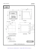
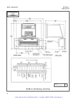
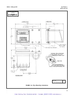
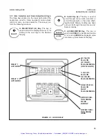
2.3.1 Panel Mounting (Standard).
The Model 1054B
is designed to fit into a DIN standard 137.9 mm X
137.9 mm (5.43 in. X 5.43 in.) panel cutout (refer to
Figures 2-1 and 2-2).
1.
Prepare the analyzer as described in Section 2.3.
2.
Install the mounting latches as shown in Figure 2-
2 (latches are shown oversize for clarity). If the
latches are not installed exactly as shown, they
will not work correctly. The screws provided are
self-tapping. Tap the screw the full depth of the
mounting latch (refer to side view) leaving a gap
greater than the thickness of the cutout panel.
3.
Align the latches as shown and insert the analyz-
er enclosure through the front of the panel cutout.
Tighten the screws for a firm fit. To avoid damag-
ing the mounting latches, do not use excessive
force.
4.
Replace the front panel assembly. Circuit boards
must align with the slots on the inside of the enclo-
sure. Replace the door and four front panel screws.
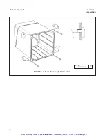
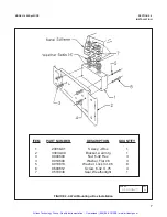
2.3.2 Wall Mounting (P/N 23054-01).
Refer to
Figures 2-3 and 2-4. The integral preamp (P/N
23363-00) should not be used with this option.
1.
Prepare the analyzer as described in Section 2.3.
2.
Mount the junction box and bracket to the analyz-
er with the hardware provided. All wiring can be
brought to the terminal strip prior to mounting the
analyzer.
3.
Place the metal stiffener on the inside of the ana-
lyzer and mount the two ¼-inch conduit fittings
using two each weather seals as shown. Mount
NEMA 4X conduit plug (included) into center con-
duit hole.
4.
Mount the analyzer to the junction box using the
1/2
-inch conduit fittings.
5.
Complete wiring from the 1054B to the junction
box (Figure 2-4).
2.3.3 Pipe Mounting (P/N 23053-00).
The 2-inch pipe
mounting bracket includes a metal plate with a cutout
for the 1054B refer to Section 2.3 for mounting the
analyzer into the plate. Mounting details are shown in
Figure 2-5.
2.3.4 Wall Mounting Enclosure (Option -20).
Refer
to Figure 2-8. In this configuration, the analyzer is
housed in NEMA 4X heavy duty enclosure and may
be mounted on a wall or handrail. Sufficient clearance
should be provided in front of the enclosure to permit
opening the door, which is hinged on the left side.
Artisan Technology Group - Quality Instrumentation ... Guaranteed | (888) 88-SOURCE | www.artisantg.com


