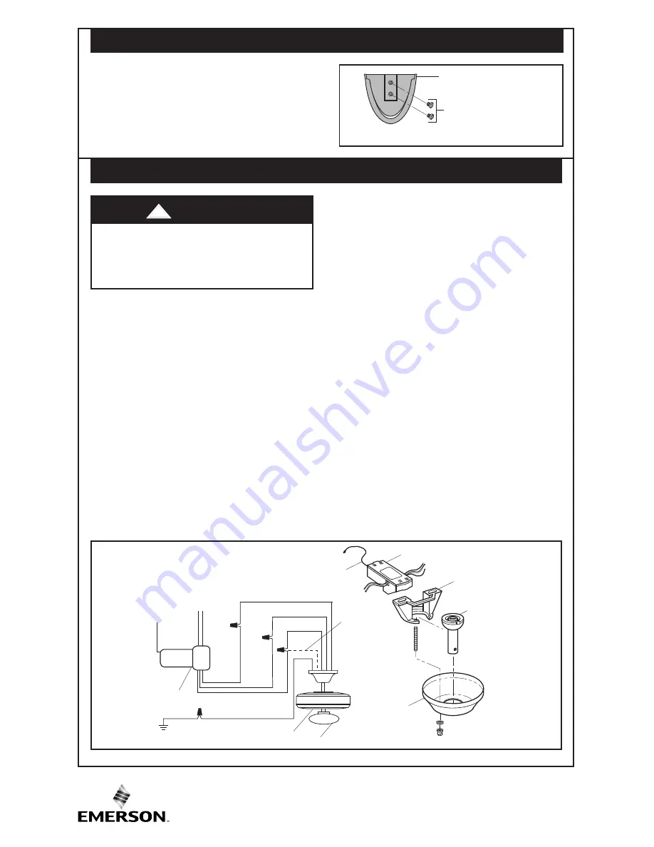
7. Installation of Storage Bracket
(Figure 4)
4
U.L. Model No: MR101F
STORAGE BRACKET
STORAGE BRACKET
SCREWS (2)
Figure 4
A storage bracket is provided for holding your
transmitter when not in use. If you desire to
use the storage bracket, install it on a wall
that is away from excess heat or humidity.
Use the two screws provided with storage
bracket.
BARE
GREEN/GROUND
AN
TE
NN
A
W
HI
TE
TO
AC SUPPLY
WHITE
BLACK
BLUE
BL
AC
K
BL
UE
RECEIVER
RE
D
HANGER
BALL
CEILING
COVER
ANTENNA
HANGER
BRACKET
RECEIVER
W
HI
TE
FAN HOUSING
LIGHT
YELLOW
(if present)
Note:
Make all wiring connections using only
listed wire connectors (supplied). Make sure
all connections are tight, including ground,
and no bare wire is visible at the wire
connectors, except for the supply circuit
ground wire.
1.
After electricity has been turned off at main
fuse box or circuit breaker box, remove the
ceiling cover from the hanger bracket.
2.
Disconnect the supply wiring to the fan by
removing wire connectors.
Note:
Do not disconnect the BARE/GREEN
GROUND wires.
3.
Connect the supply BLACK wire to the
receiver RED wire (AC IN L).
4.
Connect the supply WHITE wire to the
receiver WHITE wire (AC IN N).
To avoid possible electrical shock, be
sure electricity is turned off at the
main fuse or circuit breaker box
before installing the receiver.
5.
Connect the receiver WHITE wire
(TO MOTOR N) to the fan WHITE wire.
6.
Connect the receiver BLACK wire
(TO MOTOR L) to the fan BLACK wire.
7.
Connect the receiver BLUE wire (FOR
LIGHT) to the fan BLUE wire and fan
YELLOW wire (if present).
Note:
This wiring configuration will control
the up light and down light together.
A maximum of 300W total lighting can be
used with this receiver. Exceeding this
wattage will damage the receiver and void
the warranty.
CAUTION: If no light exists on your
ceiling fan, cap the BLUE wire on the
receiver with a wire connector.
8.
Push the connected wires up into the
junction box and position the receiver in
the hanger bracket above the hanger ball.
Lay the antenna wire on top of the
receiver.
9.
Reinstall the ceiling cover and restore
electrical power to the circuit.
Figure 5
8. Installation of Receiver
(Figure 5)
WARNING
!


