3
PENBERTHY
MODELS GL AND GH GAS OPERATED JET PUMPS
INSTALLATION, OPERATION AND MAINTENANCE INSTRUCTIONS
4 INSTALLATION
Note:
The user should refer to the relevant
technical data sheet or product proposal to
obtain dimensional information for the specific
size and model of jet pump.
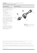
Check the exploded view (Figure 3) for the
location of operating, suction and discharge
connections to insure correct hook up.
4.1 Effect of related piping and precautions
1. Penberthy models GL and GH gas operated
jet pumps may be installed and operated in
any position.
2. Jet pumps should be installed with pipe and
fittings which provide minimum resistance
to fluid flow. Pipe line friction losses must
always be a consideration when estimating
jet pump performance.
3. It is recommended that provisions be made
for pressure gauge connections near the
inlet, suction and discharge connections
of the jet pump. If operating difficulties are
encountered at any time, it may become
necessary to install pressure gauges to
identify the problem.
4. Steam must not have over 20°F (-7°C) of
superheat, or performance will differ from
that published in the relevant technical data
sheet or product proposal referred to above.
5. When pumping liquids, suction piping
should be sized so that the velocity of the
liquid does not exceed 4 feet per second.
This is almost always obtained automatically
when the suction line is the same pipe size
as the suction connection.
6. Install a valve in the suction line if it is
desirable to:
a. Prevent contamination of suction fluid by
the motive fluid at start up.
b. Prime a centrifugal pump.
c. Throttle suction flow.
7. When a gas operated jet pump is used to lift
liquids by suction or vacuum, the jet pump
should be located as close to the level of
the liquid as practical. However, any liquid
entrained into the jet pump,
other than water
when using steam as the operating medium
,
may cause the jet pump to stop pumping,
resulting in a possible suction flow reversal.
8. Discharge piping should be sized as short as
possible and with the least number of turns
and restrictions. Discharge piping friction
losses must always be considered when
estimating jet pump performance. Increase
discharge line pipe size if necessary to
minimize loss.
9. Do not impose system piping loads on a
jet pump. The unit is NOT designed to be a
load-bearing fitting.
10. All piping should be clean and free of foreign
materials which could clog the jet pump.
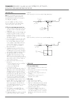
FIGURE 1
Typical installation schematic gas operated pumping gases
FIGURE 2
Typical installation schematic steam operated pumping water
Motive gas
valve
Inlet
Discharge
Motive
pressure
Suction
Suction
pressure
(vacuum)
Check
valve
Motive gas
valve
Suction
Discharge
Motive
pressure
Foot
valve
5 OPERATION
5.1 Pre-operational check
1. Ensure that all installation procedures have
been completed.
2. Ensure that any restrictions in the discharge
line have been removed.
3. Ensure that any discharge line valves are
fully open.
4. Ensure that the suction line valve, if
installed, is fully closed.
5.2 Operating
1. Open the motive valve quickly.
2. Open the suction line valve, if any.
3. Regulate the discharge pressure as desired
to a value within the capability published in
the relevant technical data sheet or product
proposal referred to above.
4. For pump priming applications, when
evacuation is completed, close the suction
valve and immediately start the centrifugal
pump. Then shut off the motive valve to the
jet pump.
Inlet

