
4
PENBERTHY
MODELS GL AND GH GAS OPERATED JET PUMPS
INSTALLATION, OPERATION AND MAINTENANCE INSTRUCTIONS
6 MAINTENANCE
WARNING
Maintenance should only be undertaken by
qualified, experienced personnel who are
familiar with this equipment and have read and
understood all the instructions in this manual.
DO NOT proceed with any maintenance unless
the jet pump has been relieved of all pressure
or vacuum, has been allowed to reach ambient
temperature and has been drained or purged of
all fluids. Failure to follow these instructions may
cause a sudden release of pressure resulting in
personal injury or property damage.
6.1 Preventative maintenance
The following items should be evaluated
regularly by the user for purposes of
maintenance:
1. Jet pump units for corrosion or debris
build up.
2. Piping and fittings for corrosion or debris
build up.
3. All connections for tightness.
4. Strainers for debris build up.
5. Units for wear.
The user must determine an appropriate
maintenance schedule most suitable for his or
her specific application, upon evaluation of their
own application and the factors stated above.
6.2 Troubleshooting (see Table 2)
TABLE 2 - TROUBLESHOOTING
Problem
Cause
Solution
The suction flow is less than expected
1. Suction piping is too restrictive
1. Remove restriction
2. Discharge pressure is too high
2. Remove restriction
3. Motive fluid pressure is lower than required
3. Increase pressure
4. Suction liquid is at much higher than ambient temperature
4. Lower temperature or size larger jet pump
5. Suction piping leaks
5. Tighten fittings
7 DISASSEMBLY - REASSEMBLY
WARNING
Do not proceed with removal of the jet pump
from connecting piping unless the jet pump has
been relieved of all pressure or vacuum, has
been allowed to reach ambient temperature and
has been drained or purged of all fluids. Failure
to follow these instructions may cause personal
injury or property damage.
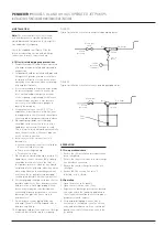
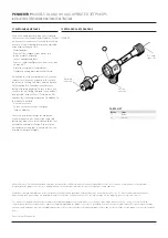
Models GL and GH jet pumps are made up of
two parts (see Figure 3): a nozzle (61) and a
body (11) which are held together by a straight
right hand mechanical thread, closing the face
seal between these parts.
To disassemble the unit, first attach a short
piece of pipe to the suction connection as a
handle, then grip the nozzle flats and rotate in a
counterclockwise direction.
When ready to reassemble the unit, be sure
the seal face of the nozzle and body are free of
foreign material and raised metal due to nicks.
A non-hardening pipe seal compound may
be applied to the threads to promote sealing
further. Thread the body back on to the nozzle
turning in a clockwise direction.
8 DISPOSAL AT END OF USEFUL LIFE
Penberthy jet pumps are used in a variety of
fluid applications. By following the appropriate
federal and industry regulations, the user
must determine the extent of preparation and
treatment the jet pump must incur before its
disposal. A Material Safety Data Sheet (MSDS)
may be required before disposal services accept
certain components.
Metal, glass and polymers should be recycled
whenever possible. Refer to order and
relevant technical data sheets for materials of
construction.