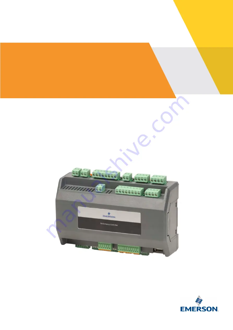
PeC Solution Controllers for
Commercial Comfort Applications
PeC C100 & PeC C200
Hardware Implementation Guidelines
Page 1: ...PeC Solution Controllers for Commercial Comfort Applications PeC C100 PeC C200 Hardware Implementation Guidelines ...
Page 2: ... 3 Installation 16 3 1 Important recommendations 16 3 2 Controller installation 16 4 Electrical connection 17 4 1 General recommendations 17 4 2 Power supply 18 4 2 1 Power supply voltage of the devices 18 4 2 2 Power supply voltage with battery backup 18 4 3 Connection of the analog inputs 18 4 3 1 Temperature probes NTC 18 4 3 2 Pressure transducers and current probes 4 20 mA 19 4 4 Connection o...
Page 3: ..._PEC_01_E_Rev01 4 8 Variable speed compressor safety chain connection 22 4 8 1 EV3 drive to PeC 22 4 8 2 Digital inputs and outputs wiring 23 5 Certification approval 24 6 Dismantling disposal 24 DISCLAIMER 24 ...
Page 4: ...ust always be kept near the controller for easy and quick reference They should be retained throughout the lifetime of the controller You are strongly advised to follow these safety instructions 1 1 Icon explanation WARNING This icon alerts the user of important instructions to avoid personal injury and material damage CAUTION This icon alerts the user of instructions to avoid property damage and ...
Page 5: ... of the mentioned system standard with the usage of flammable refrigerants The usage in systems with flammable refrigerants is limited to systems which are based on the IEC 60335 2 40 standard Systems that are using flammable refrigerants A2L and A3 must consider the following points The controller mounting area must be in Zone 2 or outside any ATEX zone and in line with Pollution Degree 2 classif...
Page 6: ... in order to store the product correctly Under no circumstances is the device to be opened the user does not require the internal components Please contact qualified service personnel for any assistance Prevent the device from being dropped knocked or shaken as either can cause irreparable damage Do not clean the device with corrosive chemical products solvents or aggressive detergents The device ...
Page 7: ...are stored in a permanent flash memory no data is lost in case of power failure local data logging function on serial flash memory RS485 Master Modbus RTU 2 x RS485 Slave Modbus RTU USB port 2 2 Main features 2 2 1 Hardware technical data Technical data Values type Operating temperature 20 to 60 C Humidity max 80 not condensing Relative humidity 20 to 85 Power supply 24 VAC 10 fuse 3 15 A slow 50 ...
Page 8: ...k colour Green LED to indicate the presence of power supply Backup power supply for EXV closing in case of power failure Voltage supply range 18 30 VDC for min 10 sec Current requirements are dependent on number and type of EXV Dry contact potential free 24 240 VAC DC opto isolated feedback safety Connector for relay 5 A resistive 3 A inductive cos φ 0 5 Relay DO1 5 6 230 V potential free Relay DO...
Page 9: ...supply Reference 18 30 VDC for min 10 sec 4 Backup supply 24 VDC Input backup power supply Reference 18 30 VDC for min 10 sec 5 RL1 NO Relay 1 NO contact 6 RL1 C Common relay 1 230 VAC max 5 A resistive 2 A inductive cos φ 0 5 switching capability 7 RL2 NO Relay 2 NO contact 8 RL2 C Common relay 2 230 VAC max 5 A resistive 2 A inductive cos φ 0 5 switching capability 9 RL3 NO Relay 3 NO contact 10...
Page 10: ...GND 40 GND Analog input GND 41 PB3 Analog input 3 TP1 NPx 42 PB4 Analog input 4 TP1 NPx 43 PB5 Analog input 5 TP1 NPx 44 PB6 Analog input 6 TP1 NPx 45 PB7 Analog input 7 TP1 NPx 46 PB8 Analog input 8 TP1 NPx 47 PB9 Analog input 9 TP1 NPx 48 10 V Analog input 0 10 Volt 49 GND GND reference 0 10 Volt 50 RS485 RS485 Master connection 51 RS485 RS485 Master connection 52 GND Ground reference for RS485 ...
Page 11: ...tection time 100 ms Table 5 2 3 1 5 Digital outputs Type Relays with NO contacts Number of outputs 4 Type of output configurable via software parameter Relays with normally open contact except LD1 that is normally closed Maximum load 230 VAC 5 A resistive 2 A inductive cos φ 0 5 Caution Verify the capacity of the output used There is double insulation between the digital outputs and the low voltag...
Page 12: ...nectors STELVIO CPM series board STELVIO CPF series disconnectable Microprocessor LPC1766 32 bit 100 MHz Permanent FLASH memory 256 KB RAM 64 KB Internal clock 100 MHz Table 7 2 3 1 9 Plastic container Mount On a DIN rail EN 50022 DIN 43880 Fastened with screws via the removable plastic flaps Material PC ABS Thermoplastic Self extinguishing V0 UL94 Comparative Tracking Index CTI 300 V Colour Grey ...
Page 13: ...ure Voltage supply range 18 30 VDC for min 10 sec Current requirements are dependent on number and type of EXV Dry contact potential free 24 240 Volt AC DC opto isolated feedback safety Connector for relay Relay DO1 5 6 230 V potential free Relay DO2 7 8 230 V potential free Relay DO3 9 10 230 V potential free Relay DO4 11 12 230 V potential free Connector for bipolar valve circuit 1 PE connection...
Page 14: ...DO8 68 69 230 V potential free Connector for bipolar valve circuit 2 Analog input connector PB10 PB11 4 20 mA related to circuit 2 Analog input connector T8 to T17 NTC Table 9 2 3 2 2 Inputs and outputs description Input no Type of input Description 1 Supply 24 VAC Power supply 2 Supply 24 VAC Power supply 3 Backup supply Backup power supply Reference 18 30 VDC for min 10 sec 4 Backup supply Backu...
Page 15: ... 33 V Power supply pressure transducer 24 VDC output Future use 5 VDC supply for ratiometric pressure transducer 34 PB2 Analog input 4 20 mA Future use 0 5 VDC signal input for ratiometric pressure transducer 35 GND GND reference for ratiometric pressure transducer for future use 36 GND Analog input GND 37 GND Analog input GND 38 GND Analog input GND 39 GND Analog input GND 40 GND Analog input GND...
Page 16: ...GND GND reference for ratiometric pressure transducer for future use 83 V Power supply pressure transducer 24 VDC output Future use 5 VDC supply for ratiometric pressure transducer 84 PB11 Analog input 4 20 mA Future use 0 5 VDC signal input for ratiometric pressure transducer 85 GND GND reference for 5VDC 24VDC and analog inputs 86 GND Analog input GND 87 GND Analog input GND 88 GND Analog input ...
Page 17: ...on time 1 second Table 12 2 3 2 5 Digital outputs Type Relays with NO contacts Number of outputs 8 Type of output configurable via software parameter Relays with normally open contact Maximum load 230 VAC 5 A resistive 2 A inductive cos φ 0 5 Caution Verify the capacity of the output used There is double insulation between the digital outputs and the low voltage of the rest of the circuit Gas tigh...
Page 18: ...256 KB RAM 64 KB Internal clock 100 MHz Table 14 2 3 2 9 Plastic container Mount On a DIN rail EN 50022 DIN 43880 Fastened with screws via the removable plastic flaps Material PC ABS Thermoplastic Self extinguishing V0 UL94 Comparative Tracking Index CTI 300 V Colour Grey Table 15 2 4 USB RS485 Adapter optional accessory The PeC controllers can be connected to a computer via an Emerson external ad...
Page 19: ...ronments where the following situations are present temperature and humidity outside the range stipulated in the data plate frequent and sudden changes in temperature and or humidity direct sunlight and weathering in general high mechanical stress vibrations and or knocks sulphur and ammonia gas smoke and salt spray that can cause corrosion and or oxidation dust no direct airstream over electronic...
Page 20: ...ower supply are separated and sufficiently distant from each other without crossing or intertwining with each other Separate the power of the controller from the rest of the electrical devices connected inside the electrical panel The secondary of the transformer must never be connected to the earth In the case of applications in industrial environments it may be useful to use the main filters in ...
Page 21: ...r the version with one EEV PeC C200 24 VAC 10 50 60 Hz consumption 50 VA for the version with 2 EEV 4 2 2 Power supply voltage with battery backup Figure 11 4 3 Connection of the analog inputs 4 3 1 Temperature probes NTC Each sensor must be connected through one of the inputs from PB3 to PB9 and the common Com as shown in the diagram in Figure 12 below Refer to Tables 3 10 for the numbering The 2...
Page 22: ...uts The digital inputs in the PeC controllers can be used as potential free digital inputs 4 4 1 Opto insulated digital inputs 24 230 VAC DC DI1 and DI4 Refer to diagrams in Figures 14 15 below and to Tables 3 10 for the numbering Figure 14 Digital inputs PeC C100 Figure 15 Digital inputs PeC C200 NOTE For A2L and A3 applications use 24 volts 4 4 2 Potential free digital input DI2 and DI3 Refer to...
Page 23: ...nd within each group For the electrical specifications refer to the relative paragraphs of the different models and to Table 13 4 6 General overview of inputs and outputs 4 6 1 Circuit 1 Top side Figure 17 Circuit 1 top side Power supply digital outputs inputs EXV connections 4 6 2 Circuit 1 Bottom side Figure 18 Circuit 1 bottom side Digital inputs Modbus communication pressure and temperature in...
Page 24: ... with fixed speed compressors only Top side Figure 19 Circuit 2 top side Power supply digital outputs EXV connections 4 6 4 Circuit 2 with fixed speed compressors only Bottom side Figure 20 Circuit 2 bottom side Pressure and temperature inputs ...
Page 25: ...rer and check the maximum current used to drive the valve 4 8 Variable speed compressor safety chain connection 4 8 1 EV3 drive to PeC Communication between the EV3 drive and the PeC controller is standard 3 wires RS485 Modbus The following connections have to be made on the EV3 drive to use Modbus control mode Enable Safety Safety Pressure Switch between pins 3 and 4 of the controller terminal Mo...
Page 26: ...igital inputs and outputs wiring for variable speed circuit proposal Figure 23 Digital inputs and outputs wiring for fixed speed circuit PeC DO8 FS Scroll 6 DO7 FS Scroll 5 DO6 FS Scroll 4 DI4 Feedback safety PeC Modbus master DO3 FS Scroll 6 DO2 FS Scroll 5 DI1 Feedback safety ...
Page 27: ... Waste Electrical and Electronic Equipment WEEE Directive 2012 19 EU and to the relative national legislation please note that There lies the obligation not to dispose of electrical and electronic waste as municipal waste but to separate the waste Public or private collection points must be used to dispose of the goods in accordance with local laws Furthermore at the end of the product s life it i...
Page 28: ...Ali Free Zone South Dubai UAE Tel 971 4 811 81 00 Fax 971 4 886 54 65 mea sales emerson com ASIA PACIFIC Suite 2503 8 25 F Exchange Tower 33 Wang Chiu Road Kowloon Bay Kowloon Hong Kong Tel 852 2866 3108 Fax 852 2520 6227 CZECH REPUBLIC Hajkova 22 CZ 133 00 Prague Tel 420 733 161 651 Fax 420 271 035 655 Pavel Sudek emerson com SPAIN PORTUGAL C Pujades 51 55 Box 53 ES 08005 Barcelona Tel 34 93 412 ...