


Oxymitter 5000
9-14
Instruction Manual
IM-106-350, Rev 2.2
July 2008
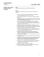
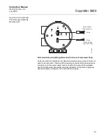
Figure 9-7. Fuse Location
6. Turn the electronic assembly over so that you are looking at the bottom
of the power supply printed circuit board. Gently depress the two white
posts one at a time. Carefully separate the power supply board (20)
from the microprocessor board (17).
7. Remove fuse (19) and replace it with a new one (Figure 9-7).
8. Align the white posts with the post holes on the power supply board and
the pin connector on the power supply board with the connector port on
the back of the microprocessor board. Gently push the boards together
until the white posts snap in place. Ensure the assembly is secure by
gently trying to separate the boards.
9. Reconnect connector J8 to the power supply board. Make sure the con-
nector is secure.
10. Holding the J1 connector leads, slide the electronic assembly the rest of
the way into the housing. Align the electronic assembly so that it fits
flush on the pins. To ensure that it is flush gently try to rotate the elec-
tronics. If the electronics rotate, repeat the alignment.
11. Reconnect the J1 connector to the microprocessor board. Ensure the
connector is secure and tighten the three captive screws on the micro-
processor board (top board).
12. Replace the housing cover and ensure that it is tight.
Entire Probe
Replacement (Excluding
Probe Head)
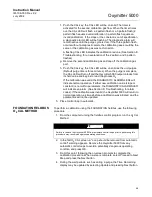
1. Do not attempt to replace the probe until all other possibilities for poor
performance have been considered. If probe replacement is needed,
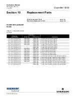
see Table 10-1 for part numbers.
2. Follow the instructions in "Removal and Replacement of Probe" to
remove the Oxymitter 5000 from the stack or duct.
3. Separate the probe and the probe head per "Replace Entire Integral
Electronics (with Housing)", steps 2 through 6.
4. Reinstall the probe head on the new probe per "Replace Entire Integral
Electronics (with Housing)", steps 7 through 13.
38730010
Fuse
Power
Supply
Board
Summary of Contents for Oxymitter 5000
Page 2: ......
Page 6: ......
Page 12: ......
Page 22: ...Oxymitter 5000 xii Instruction Manual IM 106 350 Rev 2 2 July 2008 ...
Page 42: ...Oxymitter 5000 1 20 Instruction Manual IM 106 350 Rev 2 2 July 2008 ...
Page 62: ...Oxymitter 5000 2 20 Instruction Manual IM 106 350 Rev 2 2 July 2008 ...
Page 74: ...Oxymitter 5000 4 6 Instruction Manual IM 106 350 Rev 2 2 July 2008 ...
Page 78: ...Oxymitter 5000 5 4 Instruction Manual IM 106 350 Rev 2 2 July 2008 ...
Page 94: ...Oxymitter 5000 7 6 Instruction Manual IM 106 350 Rev 2 2 July 2008 ...
Page 140: ...Oxymitter 5000 9 22 Instruction Manual IM 106 350 Rev 2 2 July 2008 ...
Page 184: ...Oxymitter 5000 B 2 Instruction Manual IM 106 350 Rev 2 2 July 2008 ...
Page 204: ...Oxymitter 5000 D 14 Instruction Manual IM 106 350 Rev 2 2 July 2008 ...
Page 222: ...Oxymitter 5000 E 18 Instruction Manual IM 106 350 Rev 2 2 July 2008 ...
Page 224: ...Instruction Manual IM 106 350 Rev 2 2 July 2008 Index 2 Oxymitter 5000 ...


