


Instruction Manual
IM-106-350, Rev 2.2
July 2008
9-11
Oxymitter 5000
Replace Entire Integral
Electronics (with
Housing)
NOTE
Only perform this procedure on units with integral electronics.
NOTE
Recalibration is required whenever electronic cards or sensing cell is
replaced.
1. Follow the instructions in "Removal and Replacement of Probe" to
remove the Oxymitter 5000 from the stack or duct.
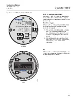
2. Remove the right housing cover uncovering the electronic assembly
(Figure 9-5).
3. Depress and remove the J1 (cell and T/C) connector from the J1 socket.
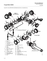
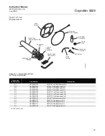
Loosen the three captive mounting screws (16, Figure 9-3 or Figure 9-4)
on the microprocessor board (top board).
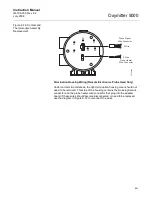
4. The J8 connector (heater leads) (Figure 9-6) can be accessed by
moving the J1 connector leads out of the slot on the microprocessor
board (17) and sliding the electronic assembly (12) partially out of the
housing (Figure 9-3 or Figure 9-4).
5. Squeeze the J8 connector on the sides and carefully remove. The
electronic assembly can now be completely removed from the housing.
6. Remove four screws (7, Figure 9-3) from the probe finned housing. The
probe and the electronic housing can now be separated.
7. When reinstalling or replacing the electronic housing make sure that
O-ring (10) is in good condition. Place the J1 and J8 connectors in the
hole on the flat side of the electronic housing.
8. Hold the J1 and J8 connectors out and to the probe side of the
electronic housing. Make sure that the conduit port of the electronic
housing is on the same side as the CAL and REF gas ports. Replace
the four screws and tighten.
9. Reconnect the J8 connector to the power supply board. Make sure the
connector is secure.
10. Holding the J1 connector leads, slide the electronic assembly the rest of
the way into the housing. Align the electronic assembly so that it fits
flush on the pins. To ensure that it is flush, gently try to rotate the
electronics. If the electronics rotates, repeat the alignment.
11. Reconnect the J1 connector to the microprocessor board. Ensure the
connector is secure and tighten the three captive screws on the
microprocessor board (top board).
12. Replace the housing cover and ensure it is tight.
13. Follow the instructions in "Removal and Replacement of Probe" to
install the Oxymitter 5000 into the stack or duct.
Summary of Contents for Oxymitter 5000
Page 2: ......
Page 6: ......
Page 12: ......
Page 22: ...Oxymitter 5000 xii Instruction Manual IM 106 350 Rev 2 2 July 2008 ...
Page 42: ...Oxymitter 5000 1 20 Instruction Manual IM 106 350 Rev 2 2 July 2008 ...
Page 62: ...Oxymitter 5000 2 20 Instruction Manual IM 106 350 Rev 2 2 July 2008 ...
Page 74: ...Oxymitter 5000 4 6 Instruction Manual IM 106 350 Rev 2 2 July 2008 ...
Page 78: ...Oxymitter 5000 5 4 Instruction Manual IM 106 350 Rev 2 2 July 2008 ...
Page 94: ...Oxymitter 5000 7 6 Instruction Manual IM 106 350 Rev 2 2 July 2008 ...
Page 140: ...Oxymitter 5000 9 22 Instruction Manual IM 106 350 Rev 2 2 July 2008 ...
Page 184: ...Oxymitter 5000 B 2 Instruction Manual IM 106 350 Rev 2 2 July 2008 ...
Page 204: ...Oxymitter 5000 D 14 Instruction Manual IM 106 350 Rev 2 2 July 2008 ...
Page 222: ...Oxymitter 5000 E 18 Instruction Manual IM 106 350 Rev 2 2 July 2008 ...
Page 224: ...Instruction Manual IM 106 350 Rev 2 2 July 2008 Index 2 Oxymitter 5000 ...


