NetSure
™
-48 VDC Power System
User Manual, UM582137200
Spec. No: 582137200
Document Code: UM582137200
Model No: NetSure™ 5100
Revision A, January 11, 2017
[2 of 17]
ESTOP Function
If an ESTOP switch is wired to the IB2 Controller Interface Board,
customer-furnished system ground applied to terminal Digital
Input #8 (+) activates the ESTOP function. The ESTOP function
shuts down and locks out the rectifiers and opens the LVD’s. When
the ESTOP signal is removed, LVD’s close after the “LVD Reconnect
Delay” has elapsed (customer configurable via the controller) (if
battery is present or after the rectifiers are restarted). To restart
the rectifiers, turn input power to the rectifiers OFF, wait 30
seconds or more (until the LEDs on the modules extinguish), then
turn input power to the rectifiers ON.
Controller Battery Charge Current Limit Feature
Functionality: After a failure of the input source (commercial AC)
or when some battery cells are permanently damaged, the current
to the batteries can be quite extensive. To avoid overheating or
further damages to the battery, the controller can be programmed
to limit the battery current to a preset level by limiting the
charging voltage of the rectifiers. Should the battery current still
exceed a higher preset value, an alarm is issued.
The controller limits the current going to the batteries based on
the “Battery Current Limit” set point which is a percentage of the
battery capacity in C10. For example, 0.1C10 would mean 10% of
the battery capacity.
Refer to the NCU Controller Instructions (UM1M830BNA) to
program this feature. Battery charge current is limited to the value
set in the controller, as long as battery voltage is above 47 VDC.
Local Controls and Indicators
Controller and Rectifier
Refer to the controller and rectifier instructions for descriptions of
the local controls and indicators located on these units.
Maintenance
System Maintenance Procedures
It is recommended to perform the maintenance procedures listed
in
every 6-months to ensure continual system operation.
Table 1.
Maintenance Procedures to be Performed at 6-Month
Intervals
Procedure
Referenced In
Check ventilation openings for
obstructions such as dust, papers,
manuals, etc.
--
Inspect and tighten all installer's
connections.
IM582137200
Adding a Rectifier
To increase system current capacity, a rectifier module can easily
be added if an empty rectifier module mounting position is
available.
Refer to Rectifier Instructions UM1R482000e3 for a rectifier
installation procedure.
Installing a Field Expansion Rectifier Shelf
DANGER! Adhere to the “Important Safety Instructions”
presented at the front of this document.
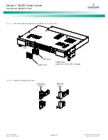
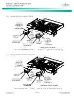
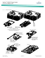
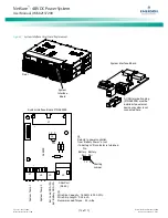
NOTE: Refer to
as this procedure is
performed.
Procedure
1.
Remove the rear shield from the main module mounting
assembly. This shield will not be re-used.
2.
When the main module mounting assembly is configured
with the front AC option, replace the mounting angle on
the left side (as viewed from the front) of the expansion
module mounting assembly with the longer mounting
angle shipped loose with the expansion module
mounting assembly.
3.
Install the expansion module mounting assembly directly
below the main module mounting assembly. Use the
mounting hardware provided with the expansion module
mounting assembly. See
for hardware build-up and recommended torque.
NOTE: Install (orient) the ground washers so the teeth
dig into the mounting angles for a secure ground
connection.
Danger


