NELSON
™
INSTALLATION
AXPTC125 POWER TEE SPLICE CONNECTION KIT
INSTRUCTIONS
TULSA, OK 74146
TEL 918-627-5530
FAX 918-641-7336
www.nelsonheaters.com
GA-5052 Rev. 3
Sheet 8 of 10
August 2017
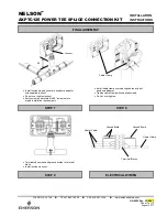
Install thermal insulation and protective lagging.
Apply sealant around standoff penetration to
prevent moisture entry.
Leave installation instructions with end user for
future maintenance and/or trouble shooting.
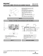
Fill in the blank fields on the label located on the
cover of the junction box as follows:
CIR. NO.
– Electrical circuit heating cable
connected too.
CAT. NO.
– Type of heating cable used
VOLTS
– Operating voltage of heating cable – Max
277VAC
AMPS
– Operating current of heating cable – Max
18A continuous current. 25A for XLT cable.
STEP 10
OPTIONAL CUSTOMER SUPPLIED POWER CONNECTION WIRING
Remove stopping plug and locknut.
Install flex conduit and drain as shown.
Terminate power and ground wires to terminal
block.
Install enclosure cover.
STEP 11
ELECTRICAL WIRING
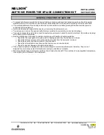
Heating cable installations require incoming power
wiring to be rated for 105ºC operation.
Maximum steady-state current may not exceed 18
amps. 25 amps for XLT cable.
Verify that all connections are properly installed
and secure.


