


NELSON
™
INSTALLATION
AXPTC125 POWER TEE SPLICE CONNECTION KIT
INSTRUCTIONS
TULSA, OK 74146
TEL 918-627-5530
FAX 918-641-7336
www.nelsonheaters.com
GA-5052 Rev. 3
Sheet 2 of 10
August 2017
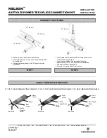
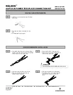
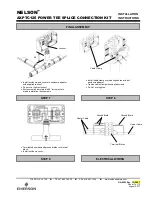
Mark pipe where standoff will be mounted.
Allow approximately
18” (46 cm) of each heating cable
for installation.
Heating cable may be cut at a 45° angle for easier
penetration.
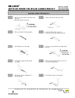
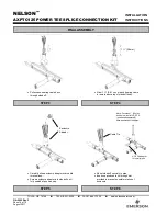
Insert cable retainer assembled with cable grommet into
standoff and clip into place.
Insert heating cables through standoff allowing
approximately 12” (31 cm) of cable for terminations.
Use cable lubricant if necessary.
Proceed to Heating Cable Terminations.
STANDOFF POSITIONING
CABLE CONSTRUCTION DETAILS
STEP 1
STEP 2
18” (46 cm)
12” (31 cm)
18” (46 cm)
18” (46 cm)
LT / UT-1 SELF-REGULATING CABLE HLT / QLT / XLT SELF-REGULATING CABLE CLT SELF-REGULATING CABLE
Braid
Core
Bus Wire
Bonded
Dielectric
Jacket
Inner
Jacket
Outer
Jacket
Core
Bus Wire
Inner
Jacket
Tinned
Copper Braid
Outer
Jacket
Core
Bus Wire
Inner
Jacket
Bare Copper
Braid
Outer
Jacket


