background image

Major Components

3

To install the Side Panel Lock:

1.

Insert a key into the lock to use as a handle.

2.

Remove the locking nut from the cylinder.

3.

Insert the lock, cam first, into the panel. The cam should be pointed to the right.

4.

Slip the nut over the cam and tighten it onto the plastic lock cylinder.

5.

Test the lock to ensure that it operates properly.

Figure 1

Side panel lock components

2.3

Mounting Hardware

Hardware to install all options is shipped with the Knurr DCM. Bags of nuts, screws, washers and 
other mounting hardware are attached to the frame. Some mounting hardware ships inside the box 
containing the optional equipment.

• 50 each: 10-32 cagenuts, screws and rosette washers
• 20 M5 spring nuts
• 20 M5 screws
• 4mm hex Allen wrench

Side Panel Lock 
cylinder

Nut to secure Side 
Panel Lock to panel

Keys

Side Panel Lock 
cam

Summary of Contents for Knurr DCM

Page 1: ...Integrated Cabinet Solutions For Business Critical Continuity Knurr DCM Rack User Manual ...

Page 2: ...g from or preparing unit for installation This product is designed for commercial industrial use only This product is not intended for use with life support or other U S FDA designated critical devices Maximum load must not exceed that shown on the Knurr DCM rating label Operate this product in a clean indoor environment that is free of moisture flammable liquids gases and corrosive substances Ens...

Page 3: ... 3 7 2 Reverse the Door 11 3 7 3 Reverse the Door Handle 11 3 8 Side Panels Remove and Replace 12 3 8 1 Remove a Panel 12 3 8 2 Replace a Side Panel 12 4 0 OPTIONS INSTALLATION 13 4 1 Anti Tilt Kit Part 540254G1L 13 4 2 1U Tool Less Fixed Shelf Installation 14 4 3 1U Tool Less Telescopic Shelf 14 4 4 2U Locking Drawer Installation 15 4 5 Power Distribution Unit Mounting 16 4 5 1 Install Tool Less ...

Page 4: ...elf installation 15 Figure 12 Locking drawer 15 Figure 13 Small PDU mounting bracket on rack frame 16 Figure 14 Full height PDU mounting brackets 18 Figure 15 RPC BDM mounting brackets and fasteners 18 Figure 16 Installing tool less blanking panels 19 Figure 17 Cluster connections 20 Figure 18 Top cover for Knurr DCM cabinets 42U and 45U high 22 Figure 19 Dress panels along edge of cluster of Knur...

Page 5: ... on Equipment Instructions Emerson Network Power is highly interested in providing high quality equipment and clear concise instructions on installing and using the Knurr DCM and its optional equipment If you have any comments about the rack its options or instructions visit www emersonnetworkpower DCMfeedback Table 1 Rack dimensions Rack Size Dimensions in mm Height Width Depth Frame Only W Level...

Page 6: ...ed for reversible left right hinging see 3 7 1 Remove the Door and 3 7 2 Reverse the Door Each type of door swings 135 degrees Each door is perforated each is available in RAL 7021 matching the rack Doors are available in these styles and sizes 1200mm x 600mm single Part 538444G1L 1200mm x 600mm split Part 539273G1L 1200mm x 700mm single Part 538444G2L 1200mm x 700mm split Part 539273G2L 1200mm x ...

Page 7: ...ock to ensure that it operates properly Figure 1 Side panel lock components 2 3 Mounting Hardware Hardware to install all options is shipped with the Knurr DCM Bags of nuts screws washers and other mounting hardware are attached to the frame Some mounting hardware ships inside the box containing the optional equipment 50 each 10 32 cagenuts screws and rosette washers 20 M5 spring nuts 20 M5 screws...

Page 8: ...t 542665G1 contains the following tools 1 M5 Allen Wrench 1 M6 Allen Wrench 1 Torx L Key T30 The following tools are required to set up a Knurr DCM pallet jack or forklift utility knife or scissors 9 16 ratchet or wrench 6mm hex wrench Tilt Indicator shows whether the unit was been tilted beyond the allowable limit or mishandled during shipping Braces secure Knurr DCM to shipping pallet one at eac...

Page 9: ...a pallet jack or forklift to raise the Knurr DCM off the shipping pallet 6 Slide the shipping pallet out from under the rack The Knurr DCM may be positioned for installation either with the forklift by two or more people carrying it or by rolling the cabinet on its casters If the casters are to be used to move the cabinet the leveling feet must be raised by reversing Step 4 above Position the cabi...

Page 10: ...e spring on the back of the nutbar and slip it into the T slot see Figure 5 If the nutbar or spring nut does not flatten out into the slot press down on the edge of the block that is too high Properly installed nutbars and spring nuts have the thread hole section on the outer side of the T slot see Figure 5 The leaf spring holds the nutbar or spring nut in place while a screw is threaded and tight...

Page 11: ...justable for installing equipment of different sizes Accesories compatible with the 19 rails includes a tool less fixed shelf Part 002185000 L shaped depth adjustable support rail Part 542777G1 a tool less telescopic shelf Part 535809G1 and a lockable fully enclosed 2U drawer Part 011139278 Each is supplied with installation hardware T Slot in Frame Nutbar in T Slot Press leaf spring and slip edge...

Page 12: ...d the 19 rail in place at the bottom 4 Hold the 19 rail to keep it from falling and loosen the M6 screws holding the nutbar at the top of the 19 rail 5 Slide the rail as unit to the desired position making sure it is properly oriented as described in the Note above 6 Hold the rail in place then insert and tighten the quarter turn fastener in the middle of the vertical rail 7 Tighten the M6 screws ...

Page 13: ...epeat on the other side of the EIA rail frame 5 Slide the rails to their new location The rails will bind if they are not kept at a right angle to the frame 6 Tighten all hardware and reinstall the quick release mechanical fasteners Figure 7 Vertical rail repositioning 700 and 800mm cabinets Screws in T Slot in frame at bottom of cabinet Rail attached to cross brace at top left corner Screws in T ...

Page 14: ...538444G3L 42U 78 1 x 23 6 2000 x 600 78 1968 23 2 589 Part 538444G4L 78 1 x 27 6 2000 x 700 27 1 689 Part 538444G5L 78 1 x 31 5 2000 x 800 31 1 789 Part 538444G6L 45U 83 4 x 23 6 2100 x 600 83 2103 23 2 589 Part 538444G7L 83 4 x 27 6 2100 x 700 27 1 689 Part 538444G8L 83 4 x 31 5 2100 x 800 31 1 789 Part 538444G9L Table 3 Door dimensions split door Frame Size Door Dimensions in mm Part Number Heig...

Page 15: ...inge Pin Cap in the hinge 10 Repeat Steps 7 through 9 for the other hinge 11 Flip the door and slide it into place 12 Remove the unit badges from the front of the door and reattach them near what is now the top of the door 3 7 3 Reverse the Door Handle After the door has been reversed the door handle of the Knurr DCM will operate without adjustment but it will be upside down To reverse the handle ...

Page 16: ...the panel up and away from the rack Set it aside 3 8 2 Replace a Side Panel 1 Hang the side panel on the lip at the top of the Knurr DCM frame 2 Use a large flat blade screwdriver to turn each of the 10 panel retainers clockwise one fourth of a turn or 90 degrees Table 4 Optional side partition panel sizes and part numbers Height mm Depth mm Part Numbers Side Panels Partition Panels 1200 1000 5385...

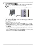
Page 17: ...the holes on the Anti Tilt Leg To move a spring nut press down on it with a small screwdriver or similar tool and slide it into position 3 The top of the Anti Tilt Leg should be positioned at the 19U mark as shown in Figure 9 4 Install one Torx head screw in the top hole 5 Install the two flathead Phillips screws in the two center holes 6 Install the remaining Torx head screw in the bottom hole Fi...

Page 18: ...the lock on one side to release it press up on the other lock to release it 3 Repeat Steps 1 and 2 for the telescopic slide on the other side of the shelf 4 Hang the telescopic slide on the rack s rails with the tabs on the upper half of the telescopic slide see Figure 11 Make sure that the front and rear tabs are level the tabs should be slots with the same number 5 Repeat Step 4 for the second t...

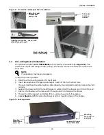
Page 19: ...ered mounting holes on the verti cal rails 3 Support the drawer so that the metal flanges on either side of the drawer are in front of the rail 4 Insert a thumb screw with a lock washer through a slot in a flange on the drawer 5 Thread it into the cagenut and tighten firmly using a hex wrench if necessary 6 Repeat Steps 4 and 5 to secure the drawer at all four mounting holes in the flanges Figure ...

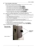
Page 20: ...ose a position near the top of 19 rail where the first tool less PDU mounting bracket will be installed 2 Hang the tool less PDU mounting bracket on a 19 rail by slipping the bracket s metal tabs into the rectangular shaped cutout on the 19 rail 3 Insert a high profile fastener into the tool less PDU mounting bracket and turn the fastener to the right to tighten it see Figure 13 4 Insert the other...

Page 21: ...t 543002G1L adjustable PDU Part 542906G1L 45U 8 wide fixed PDU Part 540085G1L To install a full height PDU bracket 1 Position the full height PDU mounting bracket for installation refer to Figure 14 for placement 2 Hold the PDU bracket in place and insert and tighten the fasteners The fastener used varies depending on the PDU bracket and PDU Fixed full height PDU mounting bracket use mechanical qu...

Page 22: ...member at top or bottom of rack The ends attach to the aluminum frame members as shown above Top of inset full height PDU bracket 4 wide Attaches to inner face of horizontal aluminum frame member at top of rack Bottom of inset full height PDU bracket 4 wide Attaches to upper face of horizontal aluminum frame member at bottom of rack Top or bottom of fixed full height PDU bracket Ends are identical...

Page 23: ... in 1U Part 010200087 and 2U Part 010200088 Attach the panels by snaping the tabs on the back into square holes in the 19 rails as shown in Figure 16 Figure 16 Installing tool less blanking panels NOTE Emerson recommends inserting blanking panels in any unused portion of the rack to promote proper airflow through the rack equipment 1U Tool Less Blanking Panel Part 010200088 Installed in Rack Front...

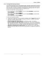
Page 24: ...the filler strips into the opening between the cabinets reduces the loss of cold air 3 Level the cabinets and make sure both frames are the same height off the floor 4 Remove the racks doors see 3 7 1 Remove the Door if necessary 5 Install a cluster bracket as shown in Figure 17 by pressing the integral pins into holes in the cabinet frame The brackets can be installed in any order starting with e...

Page 25: ...s and management provisions are built into the various Knurr DCM configurations to ease cable installation Additionally these cable management options are available to assist with routing power and control cables to reduce electromagnetic interference and to improve airflow Cable Fingers Part 010200078 Lobster Claw pack of 10 Part 002185050 pack of 100 Part 002185070 Velcro Straps pack of 10 Part ...

Page 26: ...agement unit may be installed in the center of the racks The front rear an side panels attach to the cabinet with the bolts at each corner see Figure 19 Center cable management units attach to the Knurr DCM with tabs that fit into slots on the top cover They are held in place by spring tension 1 Install the center piece first by squeezing it and sliding the four tabs into the holes in the top of t...

Page 27: ... 537887G1 800 wide cabinet Part 537877G1 Two piece Top Cover Cable Management kits for racks at the end of a row side panels only 1000 deep cabinet Part 537878G1 1100 deep cabinet Part 537879G1 1200 deep cabinet Part 537880G1 Cables can cross front to back through the center units Cables can be routed lengthwise through the center unit Panels bolt to the top of the Knurr DCM Bracket used to connec...

Page 28: ...ver The optional accessory mounts on the Knurr DCM s rails as shown in Figure 21 Insert cagenuts in rails where the radial limit will be installed attach the routing panel and pull cables through the slot Routing panels may be installed to separate cables and wiring to reduce clutter and improve airflow The optional accessory mounts on the Knurr DCM s rails much like the cable routing panel Insert...

Page 29: ...cket is needed for installing a Liebert MB modular busway on a Knurr DCM The Liebert MB provides power connections to multiple rack mounted and room power distribution units uninterruptible power systems and surge protection devices The Knurr DCM cabinets must be aligned but need not be attached in a cluster configuration Refer to the Liebert MB user manual for details on installing the power supp...

Page 30: ...st Knurr DCM in the row 2 Hold the bracket against the cabinet frame member and attach it with metal quarter turn fasteners see Figure 24 Figure 24 Liebert MB mounting bracket inserted into Knurr DCM Liebert MB mounting bracket inserted into Knurr DCM viewed from inside Knurr DCM Quarter turn fasteners inserted and tightened Slot for quarter turn fastener in T slot on cabinet frame member ...

Page 31: ...ires no special maintenance It should be cleaned periodically more frequently if the air in the vicinity is not filtered for particulates Dust should be cleaned from installed equipment according to the manufacturer s recommendations Clean the interior of the cabinet with a dry cloth ...

Page 32: ...1100mm C 47 2 1200mm FRONT DOOR 0 No Door 1 Single Perforated Door 2 Split Perforated Doors REAR DOOR 0 No Door 1 Single Perforated Door 2 Split Perforated Doors SIDE PARTITION PANELS 0 None 1 1 Side Panel 2 2 Side Panels 3 1 Partition Panel 5 1 Side Panel and 1 Partition Panel COLOR 1 Black RAL 7021 DESIGN REGION A Asia Pacific E EMEA N North America G Global A Reserved D C 6 A 1 1 2 A The sample...

Page 33: ...orated Doors 2 538444G5L 42U 2000x700 Single Perforated Door 2 539273G5L 42U 2000x700 Split Perforated Doors 2 538444G6L 42U 2000x800 Single Perforated Door 2 539273G6L 42U 2000x800 Split Perforated Doors 2 538444G7L 45U 2100x600 Single Perforated Door 2 539273G7L 45U 2100x600 Split Perforated Door 2 538444G8L 45U 2100x700 Single Perforated Door 2 539273G8L 45U 2100x700 Split Perforated Door 2 538...

Page 34: ...814G1L 42U DCM EIA Server Rail Kit for 2000mm H Two Pieces 539818G1L 45U DCM EIA Server Rail Kit for 2100mm H Two Pieces 538569G1 Hardware to Mount Components on EIA Rail 50 Each M5 Cagenuts Screws and Rosette Washers 002185000 1U Fixed Tool Less Shelf 150lb 68kg Load Rating 14 011139278 2U Locking Drawer 15 535809G1 1U Telescopic Shelf 110lb 50kg Load Rating 14 542777G1 L Shaped Depth Adjustable ...

Page 35: ...m W Cabinet Includes Front and Rear Trim Pieces 22 537887G1 Top Cover Based Cable Routing Kit for 700mm W Cabinet Includes Front and Rear Trim Pieces 22 537877G1 Top Cover Based Cable Routing Kit for 800mm W Cabinet Includes Front and Rear Trim Pieces 22 537878G1 Kit of Two Trim Pieces for Top Cover Based Cable Management 1000mm D Cabinet 22 537879G1 Kit of Two Trim Pieces for Top Cover Based Cabl...

Page 36: ... change without notice Liebert is a registered trademark of Liebert Corporation All names referred to are trademarks or registered trademarks of their respective owners Technical Support Service Web Site www liebert com Monitoring liebert monitoring emerson com 800 222 5877 Outside North America 00800 1155 4499 Single Phase UPS Server Cabinets liebert upstech emerson com 800 222 5877 Outside North...

Reviews: