


2
Keystone
Butterfly valves Paraseal
InstallatIon and maIntenance InstructIons
2.1 Valve inspection
1. Carefully remove the valve from the
shipping package (box or pallet) avoiding any
damage to the valve or, in case of automated
valves, to the electric or pneumatic/
hydraulic actuator or instrumentation.
2. Confirm that the materials of construction
listed on the valve nameplate are
appropriate for the service intended and are
as specified.
3. It is not allowed to use third party spare
parts. In case of third party spare parts,
safe operation is not guaranteed.
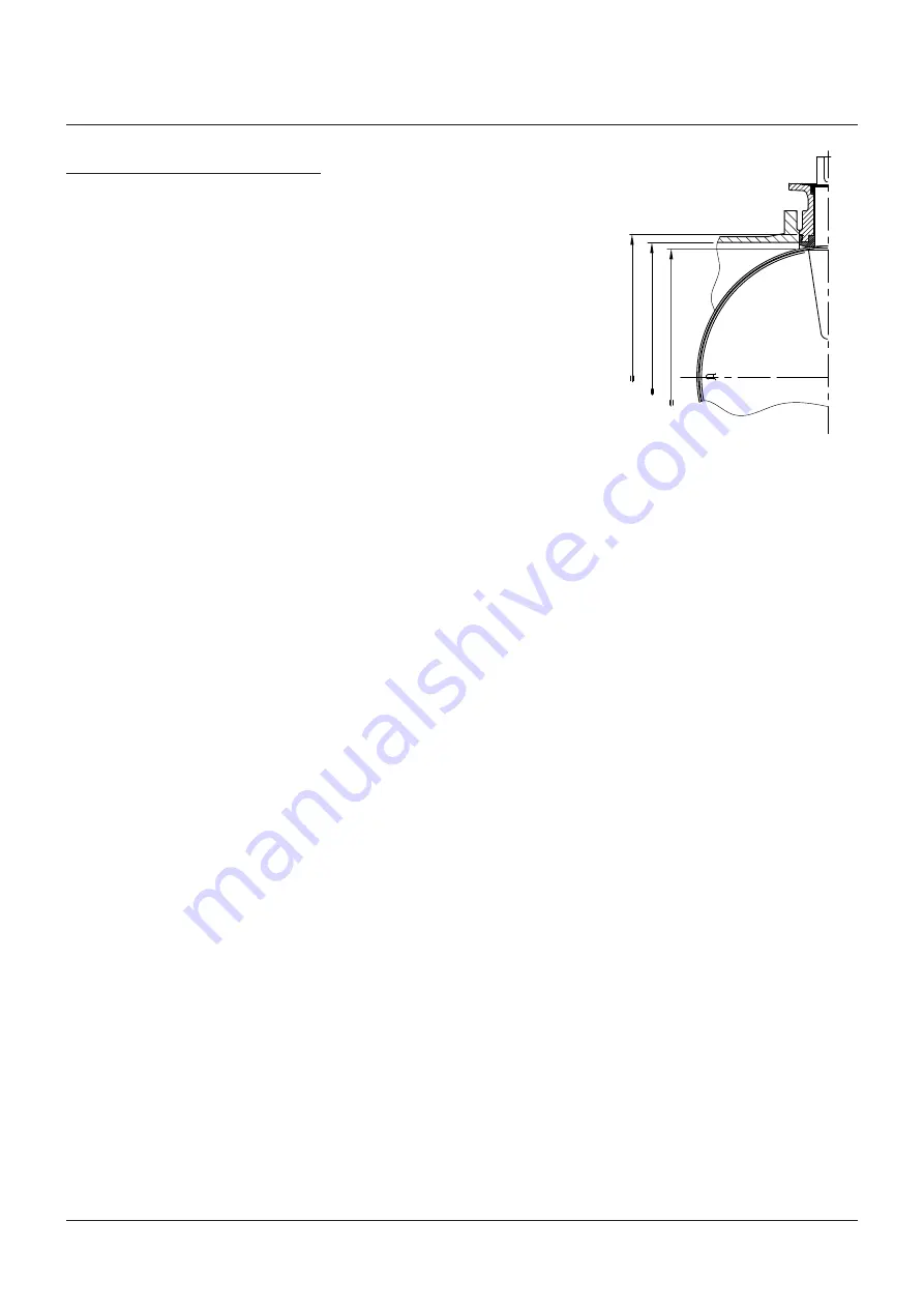
yy
D max./min.
Q
2.3 Valve installation
the valves are bi-directional and may be fitted
in either direction relative to the flow. the valve
will control flow equally in either direction. the
recommended installation position is shaft
horizontal and the lower disc edge opening
down-stream. (especially for slurry service
and media with a tendency for sedimentation).
for optimum valve control and smooth
performance, it is recommended to have a
10 to 20 pipe diameters of straight run inlet
piping and 3 to 5 pipe diameters straight outlet
piping. a valve is no crow-bar. Do not use the
valve to spread the flanges. seat damage might
be the result.
2 installation
Warning
For safety reasons, it is important to take the
following precautions before you start work on
the valve:
1. Personnel making any adjustments to the valves
should utilize suitable equipment. All required
personal protection means should be worn.
2. The line must be depressurized before
installing the valve.
3. Personnel trained in all aspects of manual and
mechanical handling techniques only must
carry out handling of the valves.
4. Misuse of the valve is not allowed. For
example: the valve, handles, actuators or other
parts may not be used as ‘climbing
tools’.
5. Ensure that valve pressure/temperature
limitations marked on the identification tag are
within the service conditions. The trim number
on the valve’s tagplate identifies the valve
materials. See Product Manual for valve specific
P/T diagram and trim number definition.
6. Ensure that valve materials are compatible
with the pipeline fluid.
2.2 Flange and pipe compatibility
Check matching of flange drilling pattern of
valve and pipe flange before assembly.
flanges have to meet the following
requirements:
-
the face inside diameter should be:
D min. : the valve Q-dim adequate
disc clearance.
D max.: the inside diameter (ID) of standard
pipe for the nominal size IsO 4200.
for larger inside pipe diameters
contact factory.
-
If the flange (or pipe) is provided with a
raised face, the diameter of this shall be at
least 10 mm larger than the yy-dimension
of the valve.
- the use of the flange gaskets is not allowed
since it might damage the valve.
- the Keystone seat face design eliminates
the need for the gaskets.
- use flange bolting in agreement with
appropriate standard.
do not use flange gaskets!


