KEYSTONE
FIGURE 79 PNEUMATIC ACTUATOR
OPERATING AND MAINTENANCE INSTRUCTIONS
© 2017 Emerson. All Rights Reserved.
Operating and Maintenance Instructions for: Figure 79 Pneumatic Actuators (U/E options)
Introduction
The Keystone Figure 79 Pneumatic Actuator
range is available in three mounting options, as
follows:-
79U - Keystone Mounting Standard
79E - ISO 5211
General Pneumatic Systems Recommendations
All Keystone Pneumatic Actuators are factory
lubricated with Molyrace LT grease and, unless
the operating environment is extremely poor,
do not require re-lubrication. To maintain
maximum efficiency with this, or other
pneumatic actuators or pressure vessels,
we advise that the following basic system
recommendations are followed:
1. Where air pipelines are subjected to
extremes of temperature, the system should
be fitted with air drying equipment.
2. Air control lines should be run to a
‘Recommended Piping Practice’ and should
not have “exaggerated” loops which may
trap condensate.
3. All pipe ends should be thoroughly cleaned
and deburred after cutting to ensure that
the pipeline is clear of cuttings.
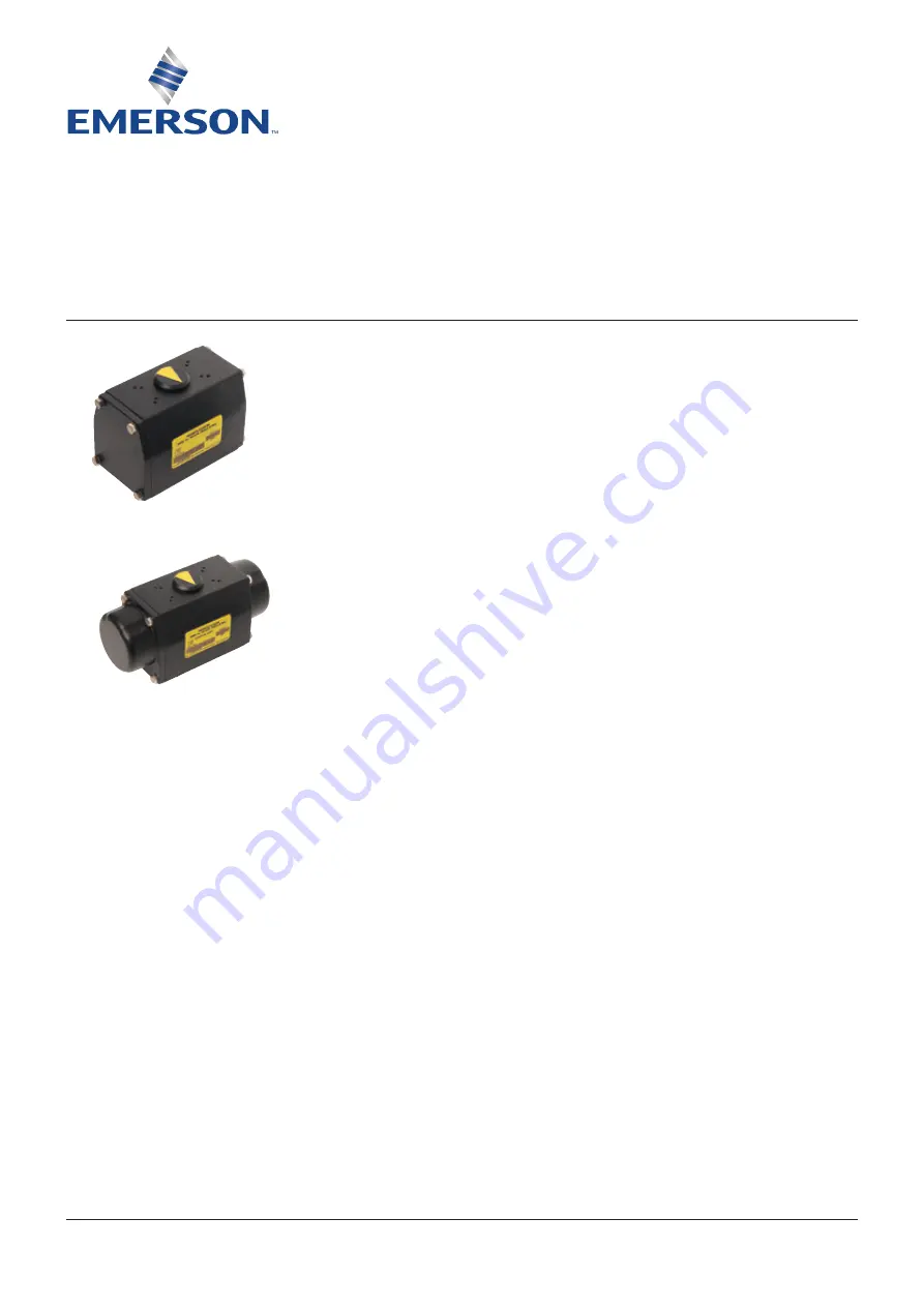
Double Acting Actuator
Single Acting Actuator
Emerson.com/FinalControl
VCIOM-01733-EN 17/04
4. If pipelines are hydraulically tested, then
the lines should be “blown down” with high
pressure air to clear all water, prior to
connecting lines to the actuator.
5. Where pipe fitting sealants are used, they
should be applied to the male threads only.
When applied to female threads, excess
compound can be transmitted into the
actuator control lines.
6. Where a system is dependent on Air Filter
Equipment, the air filters should be situated
in positions that allow easy access to
maintain and/or drain.
7. Where pneumatic valve positioners, or
pneumatic controllers are fitted to valve
actuator assemblies, oil mist lubricated air
should not be used unless the manufacturer
states specifically that the controllers are
compatible with lubricated air.
Note:
Figure 79 Actuators are rated for air
pressure in the range 40psig (2.75barg)
to 120psig (8.3barg) and can withstand a
maximum of 150psig (10barg).
Construction
Figure 79 actuators are available in a range
of sizes producing up to 27624 lb in/ 3121 Nm
output torque and are designed to be mounted
to quarter turn valves either directly or using
the correct mounting brackets/adaptors and
sizing procedures.
All models are of the opposed piston type. Each
piston incorporates a wide toothed rack which
engages a one piece drive shaft. The drive
shaft is sealbond (TM) treated for maximum
protection. The actuator body is of extruded
aluminium and is fitted with “Engineered
polymer” bearings at the drive shaft locations.
Bearing and piston seals are dynamic ‘O’-ring
type. The actuator drive is by means of a double
keyed female shaft (79U/E). A comprehensive
range of double “D” adaptors is available for
fitting to both the top and bottom of the output
shaft for accessories (top) and valve stems
(bottom).


