Instruction Manual
D200149X012
3610J and 3620J Positioners
September 2017
24
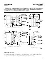
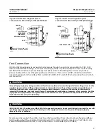
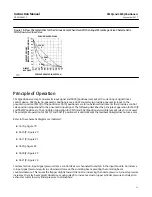
The table in figure 14 and a label inside the positioner cover (key 41, figure 28) recommend flexure adjustment
starting positions for various actuator types. Start with the flexure adjustment set to the recommended starting
distance from the gain adjustment plate, the X dimension in figure 14. To adjust the minor loop gain, proceed as
follows:
1. Unscrew the four captive cover screws and remove the cover (key 41, figure 28).
dimension between the plate and the adjustment.
flexures to increase or decrease the X dimension. Moving the flexure adjustment in the direction of the arrow on the
top flexure (decreasing the X dimension) slows the positioner response. Moving the flexure adjustment in the
opposite direction speeds up the positioner response.
4. Tighten the flexure adjustment screw and check the positioner response. Repeat step 3 if readjustment is required.
5. If this is the only adjustment, replace the cover. If not, continue with the Crossover Adjustment.
20B1277‐E
A3233‐2
GAIN ADJUSTMENT
PLATE
SOCKET HEAD
SCREW (KEY 55)
TOP FLEXURE
(RELAY BEAM
FLEXURE)
FLEXURE
ADJUSTMENT
(KEY 156)
Actuator
”X” Dimension
mm
Inches
1052/20, 2052/1
1051, 1052/30, 33, and 40, 2052/2
1051, 1052/60
1052/70
2052/3
22
24
35
38
37
7/8
15/16
1‐3/8
1‐1/2
1-7/16
1061/30
1061/40
1061/60
1061/80
21
22
24
27
13/16
7/8
15/16
1‐1/16
1061/100
1069/100
29
44
1‐1/8
1‐3/4
585C/25 and 50
585/100
33
1‐5/16
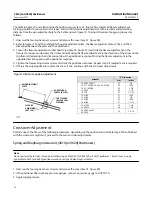
Crossover Adjustment
Perform one or the other of the following procedures, depending on the positioner and actuator type. When finished
with the crossover adjustment, proceed to the zero and span adjustments.
Spring and Diaphragm Actuators (3610J or 3620J Positioners)
Note
Do not perform these steps 1 through 6 if calibrating a 3610JP, 3611JP, 3620JP, or 3621JP positioner. These 6 steps are only
applicable to 3610J and 3620J positioners used on spring and diaphragm actuators.
1. Unscrew the four captive cover screws and remove the cover (key 41, figure 28).
2. If the positioner does not have pressure gauges, connect a pressure gauge to OUTPUT A.
3. Apply supply pressure.
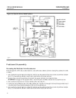
Figure 14. Minor Loop Gain Adjustment


