Instruction Manual
D200149X012
3610J and 3620J Positioners
September 2017
12
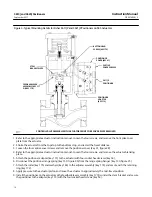
Figure 3. Typical Mounting Details for Fisher 3610J and 3620J Positioners on 2052 Actuators
ACTUATOR
COVER
PLATE
ROLLER (KEY 39)
POSITIONER
COVER
(KEY 41)
FEEDBACK LEVER
ASSEMBLY
(KEY 117)
CAM MOUNTING
MACHINE SCREWS
(KEY 83)
CAM
(KEY 82)
GG41215-A
ACTUATOR WITHOUT POSITIONER
ACTUATOR AND POSITIONER WITH
ACTUATOR COVER REMOVED
GG00138-A
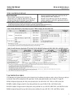
Note
Refer to the appropriate 1061 and 1069 instruction manual or contact your
information on mounting on these actuators.
Changing Cams—Actuator Styles A, B, C, and D
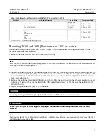
During the following procedures, refer to figure 3 for part locations and refer to figure 28 for key number locations
unless otherwise indicated. For the different actuator mounting styles, refer to the applicable instruction manual.
1. Remove the actuator cover plate from the actuator housing.


