Instruction Manual
D200149X012
3610J and 3620J Positioners
September 2017
19
For the 3611JP or 3621JP positioner, connect the OUTPUT A connection to the lower actuator cylinder connection and
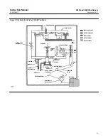
the OUTPUT B connection to the upper actuator cylinder connection. Figure 2 shows the positioner connected to a
585C actuator. Use 3/8‐inch tubing between the actuator and the positioner.
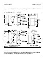
Figure 8. Typical Mounting Dimensions and Connections
OUTPUT A
CONNECTION
(PLUGGED)
208
(8.19)
63.5
(2.50)
GAUGE
BLOCK
INSTRUMENT
CONNECTION
OUTPUT A
CONNECTION
(PLUGGED ON
3610J)
OUTPUT B
CONNECTION
SUPPLY
CONNECTION
49.3
(1.94)
153.9
(6.06)
17.5
(0.69)
63.5
(2.50)
122.2
(4.81)
3622
100.1
(3.94)
208
(8.19)
208
(8.19)
63.5
(2.50)
63.5
(2.50)
103.9
(4.09)
GAUGE
BLOCK
31.8
(1.25)
BYPASS
VALVE
INSTRUMENT
CONNECTION
OUTPUT B
CONNECTION
111.3
(4.38)
SUPPLY
CONNECTION
OUTPUT A
CONNECTION
(PLUGGED ON
3620J)
OUTPUT B
CONNECTION
SUPPLY
CONNECTION
111.3
(4.38)
50.8
(2.00)
1/2 NPT
CONDUIT
CONNECTION
19A1442‐D
19A1444‐C
11B2612‐E
C0681‐3
TYPICAL 3610J POSITIONER WITHOUT BYPASS VALVE
3610J POSITIONER WITH BYPASS ASSEMBLY
3620J OR 3620JP POSITIONER
NOTE:
1INSTRUMENT, OUTPUT, AND SUPPLY CONNECTIONS ARE 1/4 NPT
mm
(INCH)
1
103.9
(4.09)
111.3
(4.38)
CENTERLINE
OF BODY
119.1
(4.69)
CENTERLINE
OF BODY
CENTERLINE
OF BODY
1
1
1
1
1
1
1
1
1
1
Instrument Connection
Use 3/8‐inch tubing to connect the output from the control device to the INSTRUMENT connection on a pneumatic
positioner. For the electro‐pneumatic positioner, refer to the Electrical Connections section.

