Memory Maps and Addresses
CPCI-6200 Installation and Use (6806800J66C
)
176
7.7.1
PCI IDSEL and Interrupt Assignment
Each PCI device has an associated address line connected via a resistor to its IDSEL pin for
Configuration Space accesses. Refer to the MPC8572, Tsi384, Tsi381 and PEX8624 datasheets
for details on generating configuration cycles on each of the PCI buses.
7.7.2
PCI Vendor and Device IDs
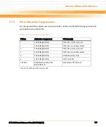
The following table shows the Vendor ID and the Device ID for each of the planar PCI devices
on the CPCI-6200.
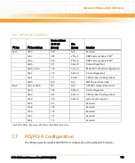
Table 7-60 IDSEL and Interrupt Mapping for PCI Devices
PCI Bus
Device
Number Field
AD Line for
IDSEL
PCI Device or Slot
Device/Slot INT to MPC8572 IRQ
INTA#
INTB#
INTC#
INTD#
PCI1 (Tsi384)
0b0_0000
20
PMC1 Primary
IRQ1
IRQ2
IRQ3
IRQ0
0b0_0001
21
PMC1 Secondary
IRQ2
IRQ3
IRQ0
IRQ1
PCI2 (Tsi384)
0b0_0000
22
PMC2 Primary
IRQ0
IRQ1
IRQ2
IRQ3
0b0_0001
23
PMC2 Secondary
IRQ1
IRQ2
IRQ3
IRQ0
PCI3 (Tsi384)
0b0_0010
18
CPCI CPLD
IRQ2
IRQ3
IRQ0
IRQ1
PCI4 (Tsi381)
0b0_0010
18
uPD720101 USB
IRQ3
IRQ0
IRQ1
NC
Table 7-61 Planar PCI Device Identification
Function
Device
Vendor ID
Device ID
System Controller
MPC8572
0x1957
0x0041
PCI-E Switch
PEX8624
0x10B5
0x8624
PCI-E-to-PCI Bridge
Tsi381
0x10E3
0x8111
PCI-E-to-PCI-X Bridge
Tsi384
0x10E3
0x8114
PCI - PCI Bridge
PCI6466
0x10B5
0x6540
USB Controller
μ
PD720101
0x1033
0x0035
Summary of Contents for CPCI-6200
Page 14: ...CPCI 6200 Installation and Use 6806800J66C 14 List of Figures ...
Page 20: ...CPCI 6200 Installation and Use 6806800J66C About this Manual 20 About this Manual ...
Page 28: ...Introduction CPCI 6200 Installation and Use 6806800J66C 28 ...
Page 44: ...Hardware Preparation and Installation CPCI 6200 Installation and Use 6806800J66C 44 ...
Page 70: ...Controls LEDs and Connectors CPCI 6200 Installation and Use 6806800J66C 70 ...
Page 106: ...MOTLoad Firmware CPCI 6200 Installation and Use 6806800J66C 106 ...
Page 178: ...Memory Maps and Addresses CPCI 6200 Installation and Use 6806800J66C 178 ...
Page 195: ......


