10
C6.2.19/0507-0708/E
4
Electrical connection
4.1
General recommendations
The compressor terminal box has a wiring diagram on the inside of its cover. Before connecting
the compressor, ensure the supply voltage, the phases and the frequency match the nameplate
data.
4.2
Electrical installation
The motor insulation material is class "B" (TF*) or "H" (TW*) for compressor models covered in
this guideline. This is according to VDE 0530, IEC 34-1 or DIN 57530.
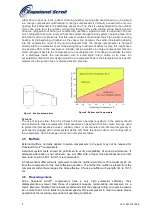
Figure 10: Power circuit single-phase
Figure 11: Power circuit three-phase
Control Circuit
A1
motor protection module
B1
room thermostat
F1
fuse
F3
high-pressure switch
F4
low-pressure switch
K1
contactor
R2
crankcase heater
S1
auxiliary switch
Y1
liquid line solenoid valve
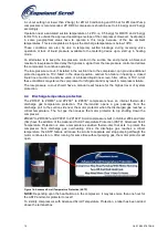
Motor Terminal Connections
Figure 12
4.2.1 Terminal box
The terminal box is IP21 for all models without electronic motor protection (eg, T
F
*/P
F
*) and
IP54 for all models with electronic motor protection (eg, T
W
*).
4.2.2 Motor winding
The ZR/ZP Scroll compressors are offered either with a single-phase or a three-phase induction
motor, depending on the size. All three-phase motors are connected in star; single-phase motors
need a run capacitor.
Summary of Contents for Copeland Scroll ZP23K Series
Page 24: ... ...


