C6.1.10/0118-0318/E
9
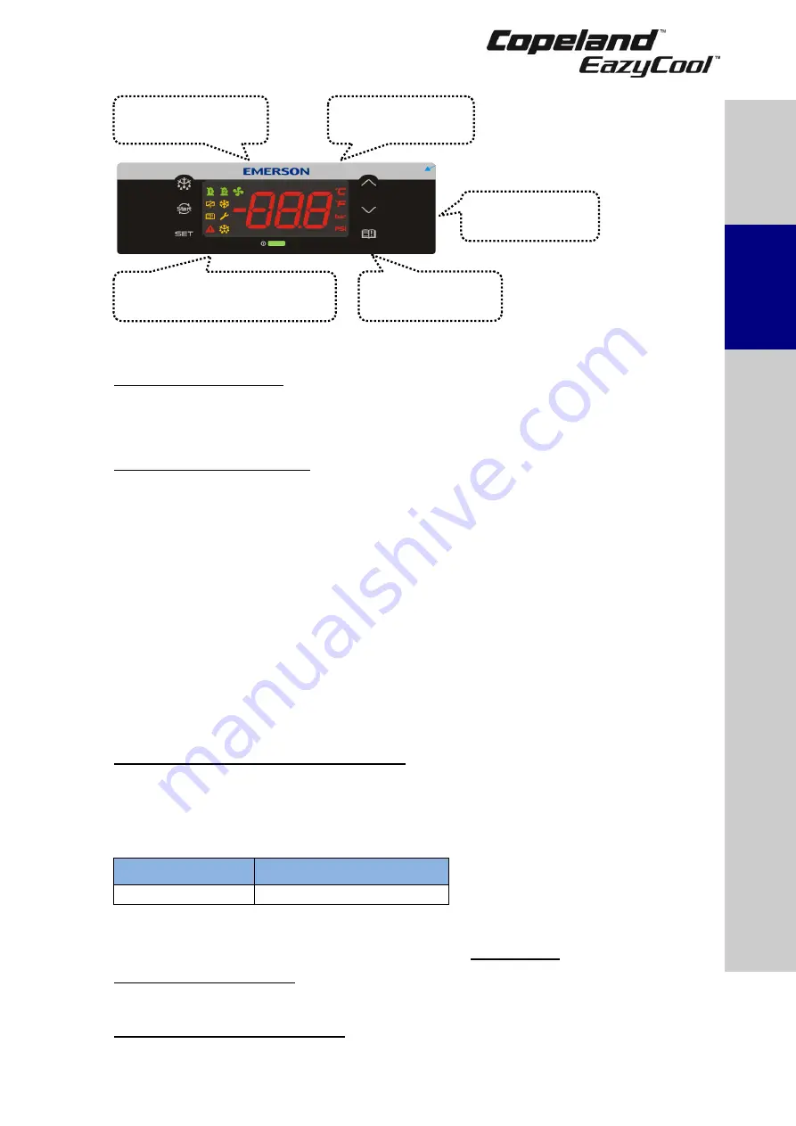
Figure 7: XCM25D controller functionality overview
2.10.3 Main control & safety features
Suction pressure control:
Each unit is equipped with a suction pressure transmitter. The
XCM25D controls the suction pressure by evaluating the input signal of the pressure transmitter.
When using a digital unit (ZXDI), the setpoint (
C16/StC
) and proportional band (
C17
/
Pbd
) need to
be adjusted. The signal of the suction pressure transmitter is also used for additional functionalities
and to keep the compressor running within the approved envelopes.
Condensing pressure control:
Each unit is equipped with a high-pressure transmitter. The
XCM25D controls the condensing pressure by regulating the fan speed corresponding to the high-
pressure transmitter signal. The output signal of the unit controller to the fan speed controller is a
0-10V signal.
The unit controller can regulate the condensing pressure in two ways. The first approach is to keep
a constant condensing temperature. This mode is utilized by the factory settings. The pre-adjusted
setpoint is 27°C as a universal setting. If lower condensing pressure is required set up the
condenser setpoint (
E39/FSP
) to a lower value.
The second control way is fan modulation based on the compressor envelope. This mode of
setpoint control is only available if a suction pressure input is not used. The parameter (
E38
/
FSM
)
enables/disables the mode as needed. If this function is unused, the condensing temperature
setpoint will be set as a parameter (
E39/FSP
) value. The compressor is allowed to run at minimum
condensing temperatures based on the suction pressure of the compressor. This is the most
energy-efficient way to minimize the condensing temperature as much as possible.
NOTE: The fan speed controller is a Ziehl-Abegg PKE-6 controller. For more information
please refer to Chapter 2.20 "Fan speed control
– Ziehl-Abegg PKE-6 controller" and to the
fan speed controller user’s guide – part of the unit standard delivery.
Maximal condenser fans pressure difference:
To provide the condenser with appropriate air
flow the pressure drop for the fan must not exceed 60 Pa at 3500 m³/h per one fan. Additional
components such as mufflers, flaps, protection grids etc... must also be taken into account when
designing the air ducts route as they will cause additional pressure drop.
The following table shows pressure drops at 3500 m³/h for most commonly used ducting
components:
Spiral duct 500 mm
Ventilation bow 90°, 500 mm
1 Pa/m
10 Pa
Table 6
Example:
If 8 meters spiral duct and 3 bows 90° are required on the installation, then
1 Pa × 8 + 10 Pa x 3 = 8 Pa + 30 Pa = 38 Pa, so
38 Pa < 60 Pa.
Compressor phase reversal:
Ensures that the compressor keeps running in one direction only
(clockwise = right rotation)
– necessary for a compliant Scroll compressor to compress and pump
refrigerant. Reset is automatic once the phase rotation is correct for the compressor.
Motor current overload protection:
This feature eliminates the need for external current
protection for the compressor motor.
Condenser fan
control
Digital Scroll
control
Alarm
management
Electrical
protection
Monitoring of the discharge
line temperature
S
afet
y
inst
ru
ctio
n
s
P
ro
d
u
ct
d
es
cr
ipt
ion
Inst
all
atio
n
S
tar
ting
up
&
o
p
er
atio
n
Ma
int
enan
c
e &
repai
r
Cer
tif
ica
tion
&
a
p
p
ro
va
l
Dismant
ling
&
d
ispo
sal


