Network Connection to E2
Network Wiring and Configuration • 11
7
Network Wiring and Configuration
If each Control Link ACC will be configured with
its own dewpoint sensor, it is not necessary to network
the Control Link ACC together. However, when
networked, multiple Control Link ACC controllers
may use a single dewpoint sensor. Furthermore,
because the Control Link ACC is a MODBUS-
compliant device, a site controller can be
programmed to communicate with the Control Link
ACC controllers via MODBUS, supporting remote
configuration and data acquisition.
The E2 controller supports networking of up to 63
Control Link ACC controllers.
7.1. Network Connection to
E2
Connecting a Control Link ACC to an E2 unit
requires the E2 to be version 2.71 or above. Contact
Emerson for upgrade information if the controller is a
version before 2.71.
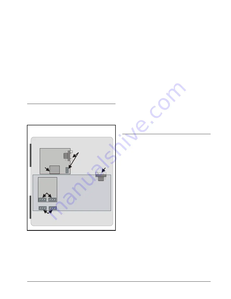
An E2 has up to three COM ports that can be
assigned for MODBUS communication (COM2, an
RS485 port on the E2 power interface board, and
COM4 and COM6, which are optional ports requiring
expansion cards). COM ports can only be used for one
function; in other words, if COM2 is set up as the I/O
network, you cannot connect MODBUS devices to
COM2. Ensure your E2 is equipped with an RS485
COM Card
(P/N 637-4890)
and configured in E2
General Services (
,
Serial
tab) to
enable COM4 or an E2 Expansion COM Card
(P/N 637-4871)
to enable COM6.
Connect the MODBUS network cable to the three-
terminal connector on the COM port you wish to
assign as MODBUS. Like other Control Link
connections, wire RS485+ to RS485+, RS485- to
RS485-, and the shield cable to the middle terminal. If
the E2 will be the first device in the daisy-chain, set
the port’s termination jumpers to the TERMINATED
& BIASED position (all three jumpers UP);
otherwise, set all jumpers DOWN if not the first
device.
7.2. E2 Setup of Control Link
ACC Devices
7.2.1. Setup Network Ports
Before setting up a Control Link ACC, the port on
the E2 that has the MODBUS cable connected must
be set up as a MODBUS port.
1. Log in to the E2 with Level 4 access.
2. Press
followed by
-
General
Controller Info
.
3. Press
+
to open the
Serial
tab of the General
Figure 7-1
-
Location of E2 COM Ports
E2 PIB COM PORT ASSOCIATIONS
COM1
COM4
COM6
COM2
Serial Device
RS485 COM Port
(2 Connectors)
RS485 COM Card
(2 Connectors)
Serial Device
RS232 Port
POWER INTERFACE BOARD
(PIB)
E2 Modem/Expansion
COM Card Mounted
Above PIB
Plug-In
Modem
Card
COM3
E2 Enclosure (Right Side)
RS485
RS232


