background image

Major Components

7

3.0

M

AJOR

 C

OMPONENTS

The Liebert GXT3 is composed of three major assemblies to provide easier handling, installation and 

versatility.

3.1

Main Frame and Electronics

All models of the Liebert GXT3 are shipped without the internal batteries installed. Power distribu-

tion varies by model and rating.

• Liebert GXT3 5000 and 6000VA models ship with a basic hardwire distribution box attached and 

ready to be connected to the load (see 

Figure 2

).

• Liebert GXT3RTL630 ships with a power distribution box attached (see (

Figure 4

).

• Liebert GXT3 8000 and 10,000VA models with a cover plate installed over connections for any of 

several optional power distribution boxes (see 

Figure 5

).

Figure 1

Liebert GXT3 front view—rack-mount and tower configurations

Figure 2

Liebert GXT3 5000VA and 6000VA rear view

Figure 3

Input power hardwire boxes—5000 and 6000VA models

NOTE

Hardwire and hardwire/receptacle boxes that include a manual bypass switch permit AC 

power to continue to flow from the utility input to the load while the box is removed from the 

UPS. For details, refer to 

3.2 - Removable Power Distribution Box

.

Status Indicators

and Controls

Lower Bezel and

Battery Access 

Door

Upper Bezel

External Battery

Connector

Liebert

IntelliSlot


Port

USB Port

Terminal Block 

Communication

Input Breaker

Knockouts for Hardwired 

Power Input

REPO

PD2-HDWR

5000 and 6000VA models 

PD2-HDWR-MBS - 5000 

and 6000VA models

Maintenance 

Bypass Breaker

Input Breaker

Input 

Breaker

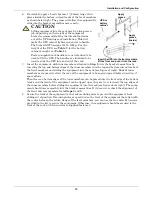
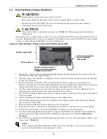
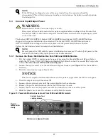
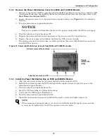
Summary of Contents for 6000RTL630

Page 1: ...AC Power For Business Critical Continuity Liebert GXT3 208V 5000 10 000VA 6000RTL630 User Manual ...

Page 2: ......

Page 3: ...ct Input Output Power 17 5 3 1 Remove the Power Distribution Box from 5000 and 6000VA Models 17 5 3 2 Remove the Power Distribution Cover from 8000 and 10 000VA Models 18 5 3 3 Install the Power Distribution Box on 5000 and 6000VA Models 18 5 3 4 Install the Power Distribution Box on 8000 and 10 000VA Models 19 5 3 5 Distribution Box Electrical Connections 19 5 4 IT Power System Configuration Lieb...

Page 4: ...PS IntelliSlot Communication Cards 29 9 3 1 Liebert MultiLink 30 9 4 Remote Emergency Power Off 30 10 0 MAINTENANCE 31 10 1 Replacing the Internal Battery Pack 31 10 1 1 Battery Replacement Procedures 31 10 2 Battery Charging 32 10 3 Precautions 32 10 4 Checking UPS Status 33 10 5 Checking UPS Functions 33 10 6 Replacing the Power Module on 8000 and 10 000VA models 33 11 0 TROUBLESHOOTING 35 11 1 ...

Page 5: ...ectors compartment 21 Figure 18 Liebert GXT3 control panel 23 Figure 19 Load level indicators 24 Figure 20 Battery level indicators 24 Figure 21 Terminal block communication pin layout 28 Figure 22 Removing the front plastic bezel cover and battery door 31 Figure 23 Disconnecting the battery plug and battery receptacle front view 31 Figure 24 Pulling out the battery packs 32 Figure 25 Removing pow...

Page 6: ...iv ...

Page 7: ...se with a four wire input L1 L2 N G The GXT3 6000RTL630 is designed be used with a three wire two phase utility source L1 L2 G WARNING The battery can present a risk of electrical shock and high short circuit current The following precautions should be observed when replacing the battery pack Wear rubber gloves and boots Remove rings watches and other metal objects Use tools with insulated handles...

Page 8: ...contain no user serviceable parts except the internal battery pack and the Power Module The UPS On Off push buttons do not electrically isolate internal parts Under no cir cumstances attempt to gain access internally due to the risk of electric shock or burn Do not continue to use the UPS if the front panel indications are not in accordance with these operat ing instructions or the UPS performance...

Page 9: ...rtant instructions AC input AC output Requests the user to consult the manual Indicates the unit contains a valve regulated lead acid battery Recycle DC voltage Equipment grounding conductor Bonded to ground AC voltage ON Alarm Silence Manual Battery Test OFF Bypass WEEE i PbH2SO4 R ...

Page 10: ... line UPS continuously conditions and regulates its output voltage whether utility power is present or not It supplies connected equipment with clean sinewave power Sensitive electronic equipment operates best from sinewave power For ease of use the Liebert GXT3 features a light emitting diode LED display to indicate both load percentage and battery capacity It also provides self diagnostic tests ...

Page 11: ...g not being protected by the Liebert GXT3 2 3 Inverter In normal operation the inverter utilizes the DC output of the power factor correction circuit and inverts it into precise regulated sinewave AC power Upon a utility power failure the inverter receives its required energy from the battery through the DC to DC converter In both modes of oper ation the UPS inverter is on line and continuously ge...

Page 12: ...e connected load in the unlikely event of a UPS malfunction Should the UPS have an overload overtemperature or any other UPS failure condition the UPS automatically transfers the connected load to bypass Bypass operation is indicated by an audible alarm and illuminated amber Bypass LED other LEDs may be illuminated to indicate the diagnosed problem To manually transfer the connected load from the ...

Page 13: ...several optional power distribution boxes see Figure 5 Figure 1 Liebert GXT3 front view rack mount and tower configurations Figure 2 Liebert GXT3 5000VA and 6000VA rear view Figure 3 Input power hardwire boxes 5000 and 6000VA models NOTE Hardwire and hardwire receptacle boxes that include a manual bypass switch permit AC power to continue to flow from the utility input to the load while the box is...

Page 14: ...O Connection Block Output Breaker for L6 30R 4 Input Breaker for L6 30P 1 1 2 3 4 5 Output Breaker for L6 20R 2 and 3 Output Breaker for L6 30R 5 IT Power System Access Cover External Battery Connector Liebert IntelliSlot Port USB Port Terminal Block Communication Maintenance Bypass Switch Knockouts for Hardwired Power Input REPO Connection Block Input Breaker Switch Output Breaker Switch Cover fo...
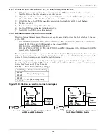
Page 15: ...PD2 002 Receptacles two 5 20R two L6 20R PD2 003 receptacles four 5 20R two L6 30 PD2 005 Receptacles four L5 20R two L6 30R PD2 004 Receptacles four L5 20R two L5 30R PD2 006 Receptacles four L6 20R L14 30 Input Power Connector Input Power Breaker Maintenance Bypass Breaker Output Power Breakers for Pigtails Push Button Output Power Breakers for Two L5 20 Receptacles second push button breaker ob...

Page 16: ...eptacles four 5 20R two L6 30R two L6 20R PD2 105 Receptacles four 5 20R two L5 30R two L5 20R PD2 106 Receptacles four L6 20R four L5 20R Output Circuit Breaker Switch for L6 30R Pigtail 1 5 20R Output Receptacles 5 20R Output Receptacles Push Button CircuitBreakers for 5 20R Receptacles L6 30ROutput Receptacles PD2 101 Receptacles two L6 30 eight 5 20R p similar features on other distribution bo...

Page 17: ...m 6 1 2 ft long Rack handles with mounting hardware Power Distribution Box installed on Liebert GXT3 Plastic tower set one Warnings safety instructions booklet and WEEE recycling sheet ISO 14001 compliance NOTE The Liebert GXT3 External Battery Cabinet shipping package includes one battery cabinet two spacers for the 5000 and 6000VA models and four spacers for the 8000 and 10000VA models for tower...

Page 18: ... able space and use considerations Determine the type of installation and follow the appropriate instructions in either 5 1 1 Tower UPS Installation or 5 1 2 Rack Mount UPS Installation 5 1 1 Tower UPS Installation To install the Liebert GXT3 as a tower 1 Take the support bases out of the accessories bag see Figure 9 Figure 9 Support bases 2 If optional Liebert external battery cabinets will be co...

Page 19: ... will use the following instructions The fig ures accompanying 5 1 3 Installing the Adjustable Rack Mount Kit Sold Separately shows the positioning of the rack mounting brackets Emerson recommends taking the internal batteries out of the UPS during rack installation This will make the UPS cabinet lighter and easier to handle 5 1 3 Installing the Adjustable Rack Mount Kit Sold Separately This kit c...

Page 20: ...rack mounting rails 4 Get eight M4 screws and eight M4 nuts from the hardware pack in this kit Each nut has a locking nylon insert that begins gripping the screw when it is halfway tight Make sure to tighten the nut and screw completely to ensure locking action Fasten the rear member and the front member together using four screws and four nuts per bracket assembly as shown in at right For maximum...

Page 21: ...ies If it does not recheck the alignment of the front and rear members from Steps 2 and 3 8 Secure the front of the equipment to the rack mounting rails to prevent the equipment from sliding out of position If securing holes are provided on the front of the equipment that align with the center holes on the return flange of the front members you can use the four extra M5 screws provided in the kit ...

Page 22: ...erify the External Battery Cabinet breaker is in the Off position 7 Connect the supplied external battery cabinet cable to the rear of the external battery cabinet then to the rear of the UPS 8 Turn the External Battery Cabinet breaker to the On position 9 Press the On button on the front of the UPS for 4 seconds to return the unit to Inverter Mode 10 Verify the circuit breaker on the External Bat...

Page 23: ... bypass 4 Turn the output and input breakers Off 5 Loosen other captive screws until the power distribution box releases 6 Remove the power distribution box from the UPS and set it aside 7 Loosen the screws over the plastic cover for the connector on the rear of the panel 8 Slide the plastic cover over the connector and tighten the screws Figure 13 Power distribution box removal from 5000 and 6000...

Page 24: ...side 7 If removing a power distribution box carefully pull apart the power distribution box connector and the UPS connector Figure 14 Power distribution box removal from 8000 and 10 000VA models 5 3 3 Install the Power Distribution Box on 5000 and 6000VA Models 1 Align the connectors and press the power distribution box onto the UPS 2 Hold the box firmly against the UPS and tighten the captive scr...

Page 25: ...d PD2 106 models fit the 8000 and 10 000VA models of the Liebert GXT3 The installer must provide an upstream branch circuit breaker The input circuit breaker on the dis tribution box and the output circuit breaker on the rear of the power distribution box disconnect all power between the main cabinet and the distribution box Models equipped with a manual bypass breaker pass bypass power directly t...

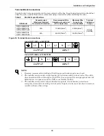
Page 26: ...0 30A 10AWG 4mm2 8AWG 6mm2 20 in lb 2 26 Nm GXT3 8000RT208 GXT3 10000RT208 60A 6AWG 10mm2 4AWG 16mm2 NOTE 1 Emerson recommends installing a UL489 approved breaker upstream of unit 2 The installer must provide circuit breaker protection according to local codes The utility disconnect should be within sight of the UPS or have appropriate an appropriate lock out Maintain service space around the UPS ...

Page 27: ...ure 3 Reinstall IT Power System Access Cover and screws Figure 17 Remove cover from IT Power System Connectors compartment WARNING Risk of electric shock Can cause injury or death Disconnect all local and remote electric power supplies before working within Ensure that the Liebert GXT3 is shut down and power has been disconnected before beginning any work on or in the unit Remove Screws IT Power S...

Page 28: ...to Restart Select frequency converter operation with a fixed output frequency of 50 or 60 Hz Set the Low Battery Warning alarm time from 2 to 30 minutes Enable Disable the Auto Battery test Set the Auto Battery test to 7 14 21 or 28 days Specify the number of external battery cabinets connected to the UPS to adjust the remaining run time calculations reported by Liebert software products Modify th...

Page 29: ...ave been retested if only three of the five Battery LEDs illuminate contact your local dealer Emerson representative or Emerson Channel Support 7 2 Standby Manual Bypass Button This button controls output power to connected load s and has dual functions Standby and Manual Bypass NOTICE Pressing the Standby Manual Bypass button once will transfer the load to bypass power and the load will be unprot...

Page 30: ...quipped with automatic and remote battery test features The default setting is for the automatic test to occur every 14 days this option is user configurable if utility power has not been interrupted Should the battery fail this test the red Fault indicator LED along with the A and C diagnostic LEDs will illuminate and an alarm will sound refer to 11 0 Troubleshooting The remote test feature funct...

Page 31: ... fault Off if there is no fault AC input Indicator Green On when the utility input power is normal Off during utility failure flashing when utility power is outside specifications Battery Indicator Amber On when the battery is supplying power Off when the battery is not supplying power Inverter Indicator Green On when the inverter is supplying power Off when the inverter is not supplying power Byp...

Page 32: ...the expected L1 N L2 voltage Verify that the same voltages appear at the Output terminals The Bypass lamp by the switch will light 8 After verifying proper input voltage to the UPS terminal block turn off the branch circuit power close all access panels to the distribution box and reapply input power 9 Close the Input circuit breaker located on the distribution box The green AC INPUT lamp should i...

Page 33: ... indica tors are illuminated refer to 11 0 Troubleshooting 8 5 Shut Down the Liebert GXT3 1 Transfer the UPS to manual bypass by pressing the Standby Manual Bypass button and holding it for about 2 seconds If manual bypass is not available disregard the first step 2 Press the Standby Manual Bypass button twice within four seconds each time holding it for about two seconds Power to the connected lo...

Page 34: ...tting down the UPS by turning off the rectifier inverter and static switch so that there is no power to the load when the UPS is On Battery The auxiliary power for the UPS will still be active Battery Mode Shutdown can be performed locally or remotely Local Battery Mode shutdown can be performed by shorting the pins in Set 4 Remote Battery Mode Shutdown can be performed using a switch connected to...

Page 35: ...lot 485 Card is used to connect the UPS and computer system Follow instructions provided with the Liebert IntelliSlot card to configure Liebert MultiLink the UPS or any additional ancillary product for the Liebert GXT3 These instructions are available at multilink liebert com NOTE Remote Power Off will be performed by NO contact The current limited source for the optocoupler 12VDC 50mA will be ava...

Page 36: ...e on four comput ers and coordinate shutdown in the event of a power failure The Liebert IntelliSlot Relay Card provides dry contact relay outputs for custom wired applications and delivers support for built in shutdown for AS 400 systems 9 4 Remote Emergency Power Off The UPS is equipped with a Remote Emergency Power Off REPO connector The user must supply a means of interfacing with the REPO cir...

Page 37: ...ttery door as shown in Figure 22 3 Lay the battery door and screws aside for reassembly Figure 22 Removing the front plastic bezel cover and battery door 4 Gently pull the battery wires out and disconnect the battery plugs and battery receptacles as shown in Figure 23 Figure 23 Disconnecting the battery plug and battery receptacle front view 5 Grasp the battery handle and pull one of the internal ...

Page 38: ...a long time Emerson recommends connecting the UPS to input power for at least 24 hours every four to six months to ensure full recharge of the batteries 10 3 Precautions Although the Liebert GXT3 has been designed and manufactured to ensure personal safety improper use can result in electrical shock or fire To ensure safety observe the following precautions Turn Off and unplug the Liebert GXT3 bef...

Page 39: ... NOTICE During the procedure the connected load will not be protected from power disturbances such as spikes sags and failure To remove the UPS power module without shutting off power to the connected load 1 Place the UPS on internal bypass This may be done by any of the three following methods a Press the Off button on the front panel one time b Slide the bracket away from the manual bypass switc...

Page 40: ...e the input circuit breaker on the rear of the UPS see Figure 7 18 Close the output circuit breaker on the rear of the UPS see Figure 7 19 Move the bypass breaker on the rear of the UPS back to the INVERTER position see Figure 7 20 Slide the bracket back next to the manual bypass breaker and tighten its thumbscrew 21 Press the On button on the front panel one time to return the UPS to Normal Mode ...

Page 41: ...eep every half second A On bypass due to overtemperature condition 1 second beep every 4 seconds B On bypass due to DC bus overvoltage 1 second beep every 4 seconds C On bypass due to DC DC power supply failure 1 second beep every 4 seconds D PFC failure 1 second beep every 4 seconds E On bypass due to inverter failure 1 second beep every 4 seconds A B UPS Failure includes dual fan failure single ...

Page 42: ...S is operating from battery mode Save data and close applications Replace UPS input fuse then restart UPS Utility power is out of tolerance UPS is operating from battery mode Save data and close applications Ensure utility supply voltage is within acceptable limits for UPS UPS has reduced battery backup time Batteries are not fully charged Keep UPS plugged in continuously at least 24 hours to rech...

Page 43: ...sentative or Emerson Channel Support Fault indicator and diagnostic A and B indicators are illuminated UPS failure includes dual fan failure single fan failure under certain conditions and battery charger failure and continuous alarm Ensure fan is not blocked up If the fault is not removed contact your local dealer Emerson representative or Emerson Channel Support AC input indicator is flashing UP...

Page 44: ...Block 3W G L L N G L1 N L2 N Maximum Allowable VAC 150VAC Output AC Parameters Factory Default VAC 120 208VAC 120 degrees L1 L2 Factory Default Output Phase Angle 120 degrees Allowable Output Phase Angle 120 180 240 degrees auto sensing on initial application of input AC Factory Default L1 N L2 N VAC 120VAC nominal User Configurable L1 N L2 N VAC 100 110 115 120 127VAC 2 L1 N L2 N Operating Load R...

Page 45: ...n box Frequency 50Hz or 60Hz Nominal Waveform Sinewave Duration Inverter Will Support Rated Load 105 to 130 1 Minute 131 to 150 10 seconds 151 to 200 1 second 200 impact load At least 5 cycles Bypass Protection Limits Disable Bypass Operation If input voltage exceeds 15 of the nominal voltage Re Enable Bypass Operation If input voltage returns to within 10 of nominal output voltage Disable Bypass ...

Page 46: ... 602 x 310 10 3 x 18 4 x 7 262 x 467 x 178 9 5 x 23 9 x 12 2 242 x 607 x 310 Weight lb kg Unit 75 8 34 4 45 4 20 6 71 1 32 3 Shipping 81 1 36 8 50 7 23 76 4 34 7 Type Valve regulated non spillable flame retardant lead acid Quantity x V x Rating 2 x 6 x 12V x 9 0 AH 20 x 12V x 9 0 AH 2 x 12 x 12V x 9 0 AH Battery Mfr Part REW45 12 Yuasa NPH5 12 REW45 12 Backup Time See Table 14 Recharge Time 3 hour...

Page 47: ...Agency Safety UL 1778 c UL Listed suitable for computer room applications RFI EMI FCC Part 15 Subpart B Class A Transportation ISTA Procedure 1A Table 12 Power distribution specifications GXT3 5000RT208 GXT3 6000RT208 and GXT3 6000RTL630 PD Model Power Distribution Box Model PD2 HDWR PD2 HDWR MBS PD2 001 PD2 002 PD2 003 PD2 004 PD2 005 PD2 006 PD2 L630 Dimensions W x D x H in mm Unit 5 2x15 5x3 5 ...

Page 48: ...6 x 8 7 302 x 522 x 220 11 9 x 20 6 x 8 7 302 x 522 x 220 11 9 x 20 6 x 8 7 302 x 522 x 220 11 9 x 20 6 x 8 7 302 x 522 x 220 11 9 x 20 6 x 8 7 302 x 522 x 220 11 9 x 20 6 x 8 7 302 x 522 x 220 Weight lb kg Unit 4 4 2 6 6 3 6 6 3 6 6 3 4 4 2 6 6 3 Shipping 6 6 3 8 8 4 8 8 4 8 8 4 6 6 3 8 8 4 Electrical Specifications Amp Rating 2 pole 60A Input Breaker Input Power Connections Hardwire Terminal Blo...

Page 49: ...attery 1 External Battery Cabinet 30 70 72 53 75 60 40 48 47 38 57 39 50 36 42 29 42 32 60 29 30 24 33 25 70 24 25 20 27 21 80 19 21 16 23 18 90 16 18 14 21 16 100 14 16 12 17 13 Internal Battery 2 External Battery Cabinet 30 110 106 86 120 92 40 78 78 72 86 70 50 60 63 48 70 52 60 48 49 41 56 41 70 40 42 35 47 34 80 34 36 28 39 29 90 30 30 24 33 26 100 25 25 21 29 23 Internal Battery 3 External B...

Page 50: ...ratures The UPS will update the anticipated run time calculation only under certain conditions The UPS must have a steady load that is greater than 20 The UPS must be at 100 charge at the start of a battery discharge The battery discharge must continue uninterrupted until the batteries reach their end of dis charge voltage If all conditions are not met the run time calculation will not be modified...

Page 51: ......

Page 52: ... change without notice Liebert is a registered trademark of Liebert Corporation All names referred to are trademarks or registered trademarks of their respective owners Technical Support Service Web Site www liebert com Monitoring liebert monitoring emerson com 800 222 5877 Outside North America 00800 1155 4499 Single Phase UPS Server Cabinets liebert upstech emerson com 800 222 5877 Outside North...

Reviews: