P8 MAINTENANCE
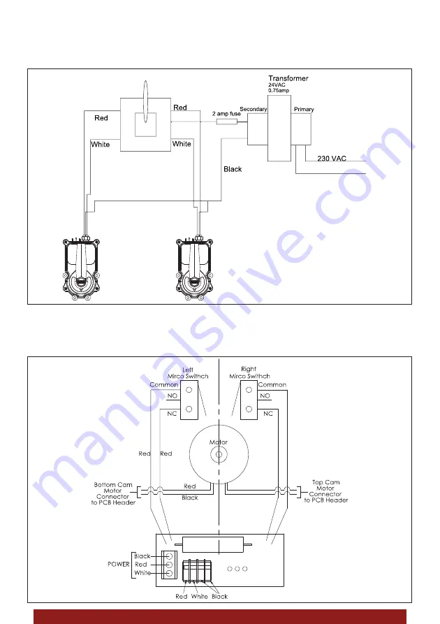
The internal circuit of the actuator is based on a motor that turns the valve, 2 limit switches, to know the
2 stop positions, a capacitor, for possible peaks in the line, and a switch controlling the tension of the
red wire (turn one way) or white wire (turn the other way).
In the following image, you can see how the connection of the 2 actuators would be. For each
connected actuator, the amperage will rise by about 1A and the fuse will have to be modified.
White
White


