


3-4
Using Your Computer
......................................................................................................................................................................................................................................
.........................................................................................................................................
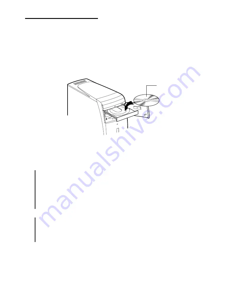
Using a CD-RW Drive
To insert a CD/CD-R(W) disc into the CD-RW drive, first turn on your system. Then push the
CD-RW drive & FDD access door to open it and press the load/eject button to open the disc tray.
When the disc tray pops out, the busy indicator light will flash. Put the CD/CD-R(W) disc in the
tray with the label side up. Press the load/eject button again or gently push the disc tray to close it.
When you want to remove the CD/CD-R(W) disc, make sure the busy indicator is off; then press
the load/eject button. When the tray pops out, remove the CD/CD-R(W) disc and then press the
button again to close the tray.
NOTES
When your system is turned off, you may need to open the tray. At this time, insert a fine rod such
as an opened paper clip into the emergency eject hole as far as it will go. When the tray is slightly
open, carefully pull it out.
You computer references the CD-RW drive as E: unless you have more than one hard disk drive or
partition. Then it automatically recognizes it as the next available drive letter.
For detailed information about using your CD-RW drive, refer to the CD-RW Drive User’s Guide.
CD/CD-R(W) disc
CAUTION
When you use the CD-RW drive, do it, with the access door opening. When you run the eject
command of the CD-RW drive or copy data to the CD-RW drive, it sometimes opens its tray
automatically. If ‘CD-RW drive & FDD access door’ is closed when the tray is opening, your
CD-RW drive may cause a problem. Using your CD-RW drive, open the access door.
Summary of Contents for emonster Series
Page 1: ......
Page 7: ...vi Blank...
Page 21: ...1 10 Introduction Blank...
Page 39: ...3 8 Using Your Computer Blank...
Page 51: ...4 12 Using the BIOS Setup Program Blank...
Page 63: ...5 12 Inside Your Computer Blank...
Page 79: ...8 4 Using the Restore CDs Blank...
Page 89: ...B 8 Solving Common Problems Blank...
Page 95: ......


