Chapter 3
101
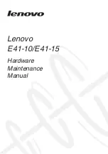
Replacing the LCD Module
1.
Place the upper cover onto the LCD module and lower into place. Lower the hinges so they are flush with the
hinge plates on the upper cover.
2.
Replace the two (2) screws to secure the left and right hinges.
Step
Size
Quantity
Screw Type
LCD Module
Assembly
M2.5*6.0-I
2
Summary of Contents for E732
Page 6: ...VI ...
Page 10: ...4 Table of Contents ...
Page 15: ...Chapter 1 5 System Block Diagram ...
Page 38: ...28 Chapter 1 ...
Page 52: ...42 Chapter 2 ...
Page 124: ...114 Chapter 3 4 Press down as indicated to secure the keyboard in place ...
Page 126: ...116 Chapter 3 ...
Page 163: ...Chapter 6 153 ...
Page 182: ...Appendix A 172 ...
Page 188: ...178 Appendix B ...
Page 190: ...180 Appendix C ...