background image

GENERAL CHARACTERISTICS

GB

PROGRAMMING

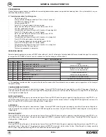
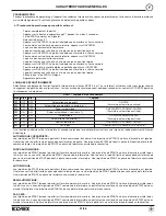
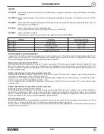
During the learning procedure, in addition to memorising deceleration spaces and pedestrian opening travel, the system detects any en-
coder position detectors present.  

4.1 Learning procedure for sliding gates

-

Close the gate fully

-

Press and hold learning pushbutton P1 for at least 3 seconds

-

The PROG LED begins to flash

-

Release pushbutton P1

-

Press APCH: the gate opens at normal speed

-

When you want the gate to move more slowly, press APCH

-

The slow speed phase begins

-

The gate then continues to move until it reaches its opening limit

-

Press APCH: the gate closes at normal speed

-

When you want the gate to move more slowly, press APCH

-

The slow speed phase begins

-

The gate then continues to move until it reaches its closing limit

-

Press APCH: the gate opens at normal speed

-

To set the partial pedestrian opening point, press APCH

-

Press APCH: the gate closes at normal speed

-

The gate then continues to move until it reaches its closing limit

-

Wait for the PROG LED to switch off

-

The learning procedure is complete.

(*) The 

courtesy

function enables the gate to be closed 5 seconds after the photocells have received a pulse, regardless of the timing of

the pause setting.  

CONDOMINIUM AUTOMATIC:

Pressing START when the gate is closed makes it open. Pressing START while the gate is opening has no effect. Once open, the gate re-
mains paused for the set pause time. Pressing START during the pause restarts the time counter from zero. Pressing START while the gate
is closing makes it open again.

SUPER AUTOMATIC:

Pressing START when the gate is closed makes it open. Pressing START while the gate is opening stops the gate; pressing START a se-
cond time makes it close again. Once open, the gate remains paused for the set pause time. Pressing START during the pause closes the
gate. Pressing START while the gate is closing makes it open again.

AUTOMATIC:

Pressing START when the gate is closed makes it open. Pressing START when the gate is opening has no effect. Once open, the gate re-
mains paused for the set pause time. Pressing START during the pause closes the gate. Pressing START while the gate is closing makes
it open again.

SEMI AUTOMATIC:

Pressing START when the gate is closed makes it open. Pressing START while the gate is opening stops the gate; pressing START a se-
cond time makes it close again. The gate remains open until START is pressed, which makes it close. Pressing START while the gate is
closing makes it open again. 

STEP BY STEP:

Pressing START when the gate is closed makes it open. Pressing START while the gate is opening stops the gate; pressing START a se-
cond time makes it close again. The gate remains open until START is pressed, which makes it close. When the gate is closing, pressing
START stops the gate and pressing START a second time makes it open again. 

OPERATING MODES

Select an operating mode by means of DSW1 dip switches 5, 6 and 7 referring to the table below (after each mode change it is necessary
to jumper the JR1 RESET contacts for a few seconds so that the change can take effect):

DWS1 – operating mode

dip 5 dip 6

dip 7

Mode

OFF

OFF

OFF

Condominium automatic

OPEN

(Automatic closing enabled)

OFF

OFF

ON

Condominium aut courtesy (*)

OFF

ON

OFF

Super automatic

OPEN-STOP-CLOSE-OPEN

(Automatic closing enabled)

OFF

ON

ON

Super aut courtesy (*)

ON

ON

OFF

Automatic

OPEN-CLOSE-OPEN

(Automatic closing enabled)

ON

ON

ON

Aut comfort (*)

ON

OFF

OFF

Semi automatic

OPEN-STOP-CLOSE-OPEN

ON

OFF

ON

Step by step

OPEN-STOP-CLOSE-STOP-OPEN

20/36

Summary of Contents for ES82

Page 1: ...onforme à la directive européenne 2004 108 CE 2006 95 CE et suivantes GB F I Art ES82 Art ES88 MANUALE PER IL COLLEGAMENTO E L USO INSTALLATION AND OPERATION MANUAL MANUEL POUR LA CONNEXION ET L EMPLOI ATTUATORE PER CANCELLI SCORREVOLI CON ANTE DA 1200 KG E 1800 KG ACTUATOR FOR SLIDING GATES WITH GATE LEAF WEIGHING 1200 KG AND 1800 KG ACTIONNEUR POUR PORTAILS COULISSANTS AVEC VANTAUX DE 1200 KG ET...

Page 2: ...cept liability for any damage caused by the incorrect installation of devices and or components not suitable for the integrity the safety and the operation of the unit The product must only be used for the purposes for which it was designed Any other use is incorrect and hence dangerous The product is not designed for use by persons inclu ding children with impaired physical sensory or men tal cap...

Page 3: ...1200 Kg 1800 Kg Alimentazione motore 230 Vac 230Vac Assorbimento medio motore 1 7 A 1 8 A Potenza 330 W 360W Giri motore 1400 1400 Condensatore 16 μF 16 μF Sblocco d emergenza Con Chiave Con Chiave Temperatura di funzionamento 20 C 55 C 20 C 55 C Peso 13Kg 13Kg Grado di protezione IP 44 IP 44 Tempo di apertura 10 mt min 10 mt min Finecorsa elettromeccanico elettromeccanico DIMENSIONI ...

Page 4: ...gio dell automatismo si verifichi che il cancello sia perfettamente funzionante Inoltre è opportuno veri ficare che la guida di scorrimento a terra V Fig 1 non presenti malformazioni che sia perfettamente a livello e che sia presente il fermo meccanico in apertura V Fig 2 al fine di evitare che il cancello esca fuori dalle guide superiori V Fig 3 Verificare la guida di scorrimento superiore V Fig ...

Page 5: ...tanza di 50 mm dal bordo del cancello e perfettamente in squadro con un an golo di 90 MPrima di fissare la piastra con cemento tasselli o altro passare la le guaine dei cavi dai fori predisposti Estrarre il carter superiore svitare le viti A e togliere la copertura B passare i cavi nella fessura del motoriduttore Fig 6 Fig 5 Fig 6 Fissare la cremagliera sul cancello in modo saldo prevedendo una di...

Page 6: ...Fine Corsa del motore sulla cremagliera Fig 8 Procedura di sblocco 1 Inserire la chiave in dotazione nell apposito cilindro e ruotare la chiave 2 Tirare la leva fino a battuta ATTENZIONE Dopo l installazione svitare di due giri la vite di sfiato Fig 8 Fig 9 Fig 10 ...

Page 7: ...7 36 SCHEDA EC40 T I COLLEGAMENTI EC40 T Lampeggiante Art ELA2 24V max 5W Lampeggiante Art ELA3 230Vc a max 40W N O ...

Page 8: ...are Se un ingresso di tipo N O è chiuso o un ingresso di tipo N C è aperto il led PROG DL9 lampeggia ad alta frequenza MESSA IN FUNZIONE Al momento della prima messa in funzione del sistema accertarsi che nessuno sia presente in prossimità del cancello automa tico A cancello chiuso il contatto N C finecorsa di chiusura morsetto n 15 deve risultare aperto led verde DL8 spento Invece se è attivo il ...

Page 9: ...iusura comanda la riapertura SUPER AUTOMATICA un impulso di START a cancello chiuso comanda l apertura Un impulso di START in fase di apertura ferma il cancello e in questo caso un successivo impulso di START comanda la richiusura Una volta aperto il cancello rimane in pausa per il tempo di sosta Un impulso di START durante la pausa comanda la chiusura Un impulso di START in fase di chiusura coman...

Page 10: ...o chiuso Uscite Descrizione N 9 2CAN N 11 Uscita secondo canale se dip 3 OFF si attiva alla ricezione del radiocomando se dip 3 ON collegare il tx fotocellule per il test N 10 AUX N 11 Luce spia Uscita tensione 24Vcc per la segnalazione remota dello stato dell automazione Se dip 22 OFF spenta a cancello chiuso altrimenti accesa Se dip 22 ON lampeggio durante i movimenti N 11 24V N 12 Uscita 24Vcc ...

Page 11: ...e Funzione Out 2CAN o apertura Pedonale In posizione di cancello chiuso premere il pulsante P2 e tenerlo premuto fino a quando il led PROG comincia a lampeggiare non rilasciare il pulsante e attendere che il lampeggio diventi più veloce Rilasciare il pulsante P2 Entro 10 secondi attivare il tasto del radiocomando da apprendere che si desidera sia associato all uscita 2CAN se dip3 OFF o al co mando...

Page 12: ...la mano vra 2 Azionare l automazione solo quando essa è completamente visibile e priva di qualsiasi impedimento 3 Non permettere a bambini o ad animali di giocare o sostare in prossimità del raggio d azione Non permettere ai bambini di giocare con i comandi di apertura o con il radiocomando 4 Non opporsi al moto dell automazione poichè può causare situazione di pericolo 5 Non toccare l apparecchio...

Page 13: ...porta un prolungamento del termine di scadenza della garanzia stessa 4 Il certificato di garanzia non copre apparecchi non funzionanti a causa di una non corretta riparazione effettuata da soggetti non qualificati le parti che presentano normale usura cattivo o diverso uso non conforme a quello indicato nel manuale di istruzione e negli schemi allegati alle apparecchiature tutti i danni causati da...

Page 14: ... 1200 kg 1800 kg Motor power supply 230 Vac 230 Vac Average motor consumption 1 7 A 1 8 A Power 330 W 360 W Motor speed RPM 1400 1400 Condenser 16 μF 16 μF Emergency release with key with key Operating temperature 20 C 55 C 20 C 55 C Weight 13 kg 13 kg Protection rating IP 44 IP 44 Opening time 10 mt min 10 mt min Limit switch electromechanical electromechanical DIMENSIONS ...

Page 15: ...ON INSTALLATION METHOD Before fitting the automation system make sue the gate is in perfect working order It is also wise to check that the runner on the ground see Fig 1 is not warped is perfectly level and that the mechanical opening stop is present see Fig 2 in order to prevent the gate from mo ving beyond the top runners see Fig 3 Mechanical stop Corner section Rounded section Make sure the to...

Page 16: ...e Gate INSTALLATION GB Make sure the wheels see Fig 4 used are suited to the runners on the ground INSTALLATION PROCEDURE Identify the gearmotor installation position Position the plate supplied Fig 5 no further than 35 mm away from the edge of the gate making sure it is perfectly square at an angle of 90 Before fixing the plate in place with cement expansion plugs or other devices run the cable s...

Page 17: ...otor limit switches to the rack Fig 8 Release procedure 1 Insert the key supplied into the relevant cylinder and turn the key 2 Pull the lever as far as it will go WARNING After installing the product loosen the vent screw by two turns Fig 8 Fig 9 Fig 10 ...

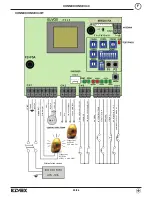
Page 18: ...LIGHT OPEN CLOSE COM 2CAN AUX 24 ACCESSORIES 24 ACCESSORIES Mains power supply OPEN CLOSE N O COMMON COMMON START PED N O STOP N C PHOTOCELL 1 N C PHOTOCELL 2 AND EDGE N C COMMON OPENING LIMIT CLOSING LIMIT Flashing light Art ELA2 24V max 5W Flashing light Art ELA3 230Vc a max 40W 18 36 ...

Page 19: ...T Switch off the power supply Disconnect all connections Remove the card by undoing the fixing screws Position the new card and fix in place Restore the connections Restore the power supply reprogram and save the radio controls Electrical connections and hook up to the mains supply The N C contacts must be jumpered to earth GND terminal when not used Otherwise the automatic gate system will NOT fu...

Page 20: ...pressing START a se cond time makes it close again Once open the gate remains paused for the set pause time Pressing START during the pause closes the gate Pressing START while the gate is closing makes it open again AUTOMATIC Pressing START when the gate is closed makes it open Pressing START when the gate is opening has no effect Once open the gate re mains paused for the set pause time Pressing...

Page 21: ... Dip 22 ON flashing during movement N 11 24V N 12 24Vdc output Photocells power supply N 4 LAMP N 5 Non intermittent output for flashing light with card Operating Description OBSTACLE WHEN CLOSING The gate immediately reverses its movement OBSTACLE WHEN OPENING The gate immediately reverses its movement for 1 5 sec and comes to a stop INPUTS OUTPUTS AND OPERATIONS DSW1 Function ON OFF dip 1 Releas...

Page 22: ...ress and hold pushbutton P2 until the PROG LED begins to flash keep holding the pushbutton down and wait for the flashing to become faster Release pushbutton P2 Within 10 seconds activate the radio control key to be learnt and associated with the 2CAN output if dip 3 OFF or with the pede strian opening command if dip 3 ON Learning procedure completion will be signalled by the simultaneous flashing...

Page 23: ...gate runner wheels and the top runner rails Make sure the rack is securely fastened clean and free from build up Clean the runner track Automation system Make sure the safety devices photocells safety edge strips etc are working properly No special maintenance is envisaged for this system However if intervention is necessary for mechanical parts always remove the actuator to enable repairs by auth...

Page 24: ...e 4 The guarantee certificate does not cover appliances not working because of a not correct repair carried out by not qualified personnel parts presenting normal wear and tear bad or different use of the appliance not in accordance with the instruction manual and the wiring diagrams enclosed with the applian ces all damages caused by natural calamities tampering and incorrect supply voltage opera...

Page 25: ...00 kg 1800 kg Alimentation moteur 230 Vca 230 Vca Absorption moyenne moteur 1 7 A 1 8 A Puissance 330 W 360 W Tours moteur 1400 1400 Condensateur 16 μF 16 μF Déblocage d urgence Avec clé Avec clé Plage de température de fonctionnement 20 C 55 C 20 C 55 C Poids 13 kg 13 kg Degré de protection IP 44 IP 44 Temps d ouverture 10 m min 10 m min Fin de course électromécanique électromécanique DIMENSIONS ...

Page 26: ...2 afin d éviter que le portail ne sorte des guides supérieurs Voir Fig 3 Vérifier que le guide de coulissement supérieur Voir Fig 3 est bien stable et que le portail coulisse librement Butée mécanique Section arrondie Section angulaire F RACCORDEMENT TYPE ET SECTION DES CÂBLES MOTEUR AVEC ÉLECTRONIQUE INCORPORÉE RX photocellule TX photocellule 2x0 75 mm2 2x0 75 mm2 4x0 75 mm2 3x1 5 mm2 Ligne 230V ...

Page 27: ...t à angle droit à 90 Avant de fixer la plaque avec du ciment des chevilles ou tout autre système faire passer la les gaine s des câbles à travers les ori fices prévus 27 36 Fig 5 Fig 6 Fig 7 Orifices de pas sage des câbles Crémaillère Contre plaque Roue Portail Sortir le carter supérieur dévisser les vis A et retirer le couvercle B passer les câbles dans la fente du moto réducteur Fig 6 Fixer ferm...

Page 28: ...urse du moteur sur la crémaillère Fig 8 Procédure de déblocage 1 Introduire la clé fournie dans le cylindre prévu à cet effet et tourner la clé 2 Tirer le levier à fond ATTENTION Après l installation dévisser la vis d évent de deux tours Fig 8 Fig 9 Fig 10 28 36 ...

Page 29: ...RES COM OUVRIR FERMER N O START PIET N O COMMUN PHOTOCELLULE 1 N F STOP N F PHOTOCELLULE 2 ET BORD N F OUVRIR FERMER CLIGNOTANT CLIGNOTANT TERRE PHASE NEUTRE COMMUN COMMUN FIN DE COURSE OUVERTURE FIN DE COURSE FERMETURE Clignotant Art ELA2 24V max 5W Clignotant Art ELA3 230Vc a max 40W 29 36 ...

Page 30: ...contraire l automatisme NE PEUT PAS fonctionner Si une entrée de type N O est fermée ou une entrée de type N F est ouverte la led PROG DL9 clignote à haute fréquence MISE EN SERVICE À la première mise en service du système s assurer que personne ne se trouve à proximité du portail automatique Lorsque la grille est fermée le contact N F de fin de course de fermeture borne n 15 doit résulter ouvert ...

Page 31: ...PER AUTOMATIQUE une impulsion de START lorsque le portail est fermé commande l ouverture Une impulsion de START en phase d ouverture arrête le por tail dans ce cas une autre impulsion de START commande la refermeture Une fois ouvert le portail reste en pause pendant le temps de pause Une impulsion de START pendant la pause commande la fermeture Une impulsion de START en phase de fermeture commande...

Page 32: ...le portail et fermé sinon allumé Si dip 22 ON clignotement pendant les mouvements N 11 24V N 12 Sortie 24 Vcc Alimentation photocellules N 4 LAMP N 5 Sortie non intermittente pour clignotant avec carte Fonctionnements Description OBSTACLE EN FERMETURE Le portail intervertit immédiatement le mouvement OBSTACLE EN OUVERTURE Le portail intervertit immédiatement le mouvement pendant 1 5 seconde et s a...

Page 33: ...ocier à la commande de START La fin de l apprentissage est signalée par le clignotement simultané de la led PROG et du voyant lumineux AUX jusqu au relâchement de la tou che de la radiocommande Répéter l opération pour chaque radiocommande à apprendre En position de portail fermé appuyer sur le bouton P2 jusqu à ce que la led PROG commence à clignoter ne pas relâcher le bouton et attendre que le c...

Page 34: ...acles 3 Ne pas permettre à des enfants ou à des animaux de jouer ou de séjourner à proximité du rayon d action Ne pas permettre à des en fants de jouer avec les commandes d ouverture ou avec la radiocommande 4 Ne pas s opposer au mouvement de l automatisme car cela peut être à l origine d une situation dangereuse 5 Ne pas toucher l appareil avec les mains et ou les pieds humides F MAINTENANCE MAIN...

Page 35: ...at La réparation ou substitution des pièces durant la période de garantie ne comporte pas un prolongement du terme d expiration de la même garan tie 4 La certification de garantie ne couvre pas appareils qui ne fonctionnent pas à cause d une non correcte réparation effectuée par personne non qualifiées les parties qui présentent normale usure mauvais ou différent emploi non conforme à celui indiqu...

Page 36: ...ION GUARANTEE CERTIFICATE Enclose with the product in case of repair under guarantee CERTIFICATION DE GARANTIE AUTOMATISMES À ajouter au produit en cas de réparation en garantie INDIRIZZO DELL UTILIZZATORE ADDRESS OF USER ADRESSE DE L USAGER Cognome Surname Prénom Nome Name Nom Via Address Adresse CAP CITTA CITY VILLE PR Tel CERT n 9110 ELVO UNI EN ISO 9001 2008 ELVOX Austria GmbH Grabenweg 67 A 6...

Reviews: