21
© 2022, Elon Group AB. All rights reserved.
Fig. 9
Fig. 10
ASSEMBLY OF PRODUCT
Drilling the Hanger Holes
Paste the installing template provided within the
product on the surface where the product is to be
installed.
Make holes with Ø4 mm diameter on the points
marked as A, B, C, D on the installing template (Fig.
9).
Drill the flue outlet hole specified in the installing
template in the sizes given.
For models that do not have built in flue discharge,
attach the plastic flue adapter to the air discharge
of the cooking hood (Fig. 9).
1- Flap Pin Socket
2- Flap Pin
Insert the plastic pin (area no.2) on the pin socket
on the motor exhaust (area no.1 ).Fig. 10(Fig. 10 Then
bend the flap lightly to insert the other pin on the
flap and insert the other pin to its socket (Fig. 10).
The hood flaps should be inserted
with the plastic tabs on the pins facing
upwards, as seen in the image (Fig.
10Fig. 10).
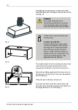
The appliance should be mounted on the cabinet on
the points A, B, C, D by using 4 x 40 screws provided
with the appliance. The front panel should not be
rubbed against the cabinet cover when the sliding set
moves (Fig. 11).
The device mounting accessories include two hood
flaps Attach these flue flaps to the motor exhaust as
seen below
Fig. 11


