

ESR Series Routers Operation Manual
13
2.4
Design
This section describes the design of the device. Depicted front, rear, and side panels of the device,
connectors, LED indicators and controls.
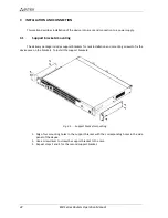
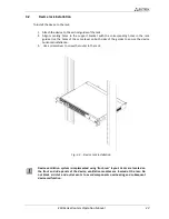
The device has a metal housing available for 19” form-factor rack mount; housing size is 1U.
2.4.1
ESR-1000, ESR-1200 design
2.4.1.1
ESR-1200 front panel
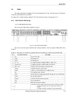
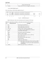
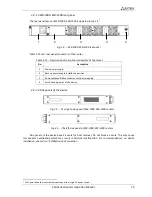
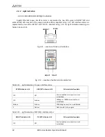
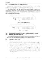
The front panel of ESR-1200 is depicted in Fig. 2.1.
Fig. 2.1 - Front panel of ESR-1200
The list of connectors, light indicators and controls located on the front panel of ESR-1200 lists in
Table 2.9
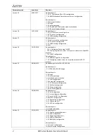
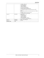
Table 2.9 - Description of connectors, indicators and controls located on the front panel of ESR-1200
№
Front panel element
Description
1
SD
SD-card connector.
2
USB1
USB-device port.
3
USB2
USB-device port.
4
[1 .. 12]
12 x Gigabit Ethernet 10/100/1000Base-T (RJ-45) ports.
5
Combo Ports
4 x Gigabit Ethernet 10/100/1000Base-X (SFP) ports.
6
XG1 - XG8
10G SFP+/ 1G SFP transceiver installation slots.
7
Status
Indicator of device's current state.
Alarm
indicator of alarm existence and emergency level.
HA
НА operation mode indicator.
Flash
Activity indicator of exchange with data storages (SD-card or USB Flash).
Power
Device power indicator.
Master
Indicator of failover modes operation.
Fan
Fan alarm indicator.
RPS
Backup power source indicator.
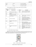
8
F
Functional key that reboots the device and resets it to factory settings:
Pressing the key for less than 10 seconds reboots the
device;
Pressing the key for more than 10 seconds resets the


