


PFA, BGT · Edition 03.11
22
6 .3 Wiring
Integrate module subracks BGT in the equipotential bonding
system.
6 .3 .1 Safety-related control signals
Signals from the safety interlocks and digital input are trans-
ferred independently of the bus communication by separate
cables.
The purge signals can be transferred via the bus communica-
tion or by a separate cable.
6 .3 .2 EMC
To achieve a high immunity of the system against electro-
magnetic interference radiation, a shielded data cable must
be used. The shield must be connected to protective earth
on both sides using wide-area shield clips that ensure good
conductivity.
In addition, it must be ensured that all cables leading to and
from the PFA be installed as far away as possible from cables
emitting strong fields (e.g. frequency converter cables).
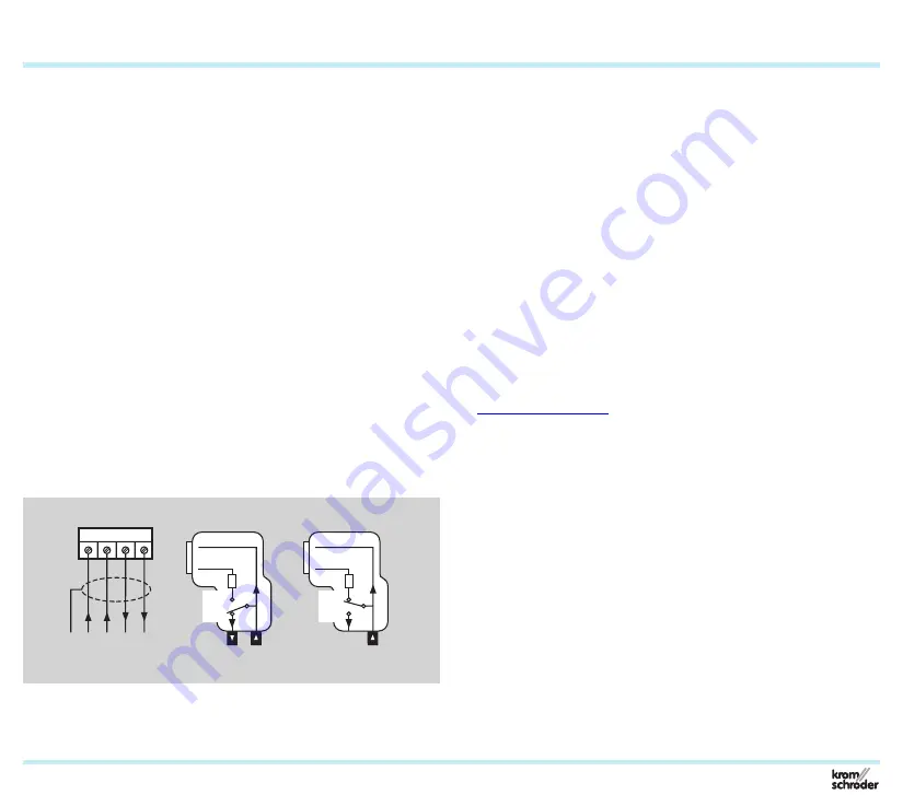
6 .3 .3 PROFIBUS plug connector
PROFIBUS-DP
A B A’ B’
OFF
ON
OFF
ON
Data cables A and B must not be reversed.
The power supply for the bus terminator is provided by the
PFA. The bus terminator can be connected in the PROFIBUS
plug connector.
Ensure an equipotential bond between the different slaves
and masters.
Bibliography
– PROFIBUS Specification, EN 50170 Vol. 2 (version 1.0).
– Installation Guideline for PROFIBUS DP/FMS, available
from the Profibus User Organization (PUO).
– PROFIBUS Technology and Application, Order No.: 4.001,
available from the PUO.
– M. Popp, The New Rapid Way to PROFIBUS DP, a textbook
for system operators.
– M. Popp, PROFIBUS DP Principles, Tips and Tricks for Us-
ers.
– www.profibus.com
6 .4 Manual operation
For emergency operation, the time-limited manual mode can
be deactivated.
The PFA is delivered with manual mode pre-set to a time limit
(parameter 34 = 1).
Project planning information